
VOM = volt ohm meter ., DVM , digital voltmeter, a analog volt meter, has a needle.
A Multimeter.
Basic usage are, checking voltage or current, and restance, for illegal voltage drops or open circuits or for short circuits.
You can check for a bad fuse, using the 20 Volt scale, turn the key on, and see that 12v is on both sides of the fuse. If not? then the fuse is blown. (this test, beats all other tests, hands down for conduction, do to live testing is REALITY)
The best usage, is for finding voltage drops. ( In the end, all connections fail, eventually "entropy")
The Basics?:
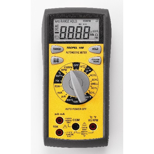
The best meter is that meter with a duty cycle function for settting, idle controls. The amp clamp meters are even better.
Walmart has nice meters for about $20.
I recommend practicing with a manual ranging meter then working up to the Auto-ranger meter. (To use an auto-ranger you must read the LCD screen and see what range the meter selected, at the time of measurement)
1.2 V means 1.2 volts
1.3 mV means 0.0013 volts or 1.3 millivolts
0.3 omega symbol (or Ω ) is 0.3 ohms or a short (if meter is auto or manually zero'd it will read 0.0 ohms.) (zero ohms means continuity is good, or near)
1.4 meg means , 1,400,000 ohms or an open circuit.
1.6 K means 1,600 ohms k means times 1000. 1.6 x 1000 = 1,600 ohms.
The meter must do Amps up to at least 10 amps. (or use the Amp clamp meter)
- See phantom drain page.
- See blows fuses, how to find short circuits.
- See more meters here.
- See the electrical fail page for help.
To that end. I will proceed.
This page is 100% focused, just on finding car electrical problems.
Rules:
- Never put the meter in to AMPS mode and then connect it directly across a battery or from any power feed wire to ground. It will blow the fuse inside the meter.
- Never uses OHMs (resistance ) mode on a hot circuit, Best is to pull battery negative lug first.
- You can use volts all day, any which way and it's all safe to do on any hot circuit of the car, but never connected to the HighVoltage spark plugs or wires, running or cranking.
- Always test the meter first and for SURE the range/mode you are using, before trusting the meter.
- Buy some back probing needles to probe connectors. Do not jam large probes, above seen in to Suzuki connnector main ports or they will get damaged. This is done by using a back probing method, with a needle.
METER TEST:
The first step always, is to make sure the meter operates. (always assume the meter is bad or its battery is bad or fuse is blown)
Some meters have a battery check, feature, the internal test. Do that now.
Set the meter to read volts , then connect the meter to a good 1.5v or 9vdc smoke detector/radio battery . do they read correctly ? Try the car battery now, is it 12.6vdc?
Some meters , low resistance range is Rx1 or Rx2, the latter is more common today. (0 to 1 ohms or 0 to 2 ohms scales)
Set the meter to ohms, Rx1 (or the lowest range) if meter is manual ranging. Short the leads together and the meter must show a short 0.0 Ω ohms or close. (most meter cheap read 0.3 ohms, but is close to zero)
(O.V, or O.R , or O.L, indicated on LCD) means infinity or the meter leads are open and not connected. O.R. is the best message , for Over Range, or over load.
Next, I grab my 1000 ohm resistor brown+black+red and read it on the Rx2k (or Rx2000 ) range. it will read about 1000 OHM's with an error not greater that 5%, if the last color code band, is gold painted.
When folks say check continuity they mean 0 ohms resistance. or near. (down a wire or past a connector or a closed switch or relay)
When they say, check for good insulaton, they are using the resistance top ohms scale for infinity, if the meter shows infinity ohms the insulation is good. ( a wire pin to ground is checked with the meter, in a no cold circuit)
We now have a good meter, using a bad one or one with a blown fuse or dead battery, this will cause you frustration.
Never fail to check your meter first. (on the mode and scale about to be USED )
We need to measure OHMS (resistance Ω) , Voltage, and Current.
I will say "OHM out" that connector , that means check its resistance for excess amounts.
When some one says , check for continuity , use the OHM meter on Rx1 range and see if the connection reads close to 0.0 ohms Ω. My meter beeps, at near that. (see to beep mode)
Some meters , low resistance range is Rx1 or Rx2, the latter is more common today. (0 to 1 ohms or 0 to 2 ohms scales)
We also call continuity, "ringing out" a connection ( in olden days, we had buzz boxes and bell boxes for doing continuity tests) Today the bell is in the meter, called a continuity beeper .
If I'm am planning to read current, I then do a current check, of the meter before my work, a real test . see the end of this page for that procedure.
One example:
The Classic , 8v injector wires check. (Rx2 means , I grab the DMM dial and pick Resistance range 2) { 0 to 2 ohms range, if you meter is an autoranging meter, read your manual, autorangers are not DIY friendly}
RTM: (read your meter manual)
There is nothing wrong with an Autoranger, but you just look on the LCD screen to see the final results and if it shows and Omega symbol Ω that means lowest range. lowest range. Also known as the "Multiplier".
So 1.06 Ω omega means 1 ohm scaled.. if the symbol is K it's 1,000 ohms. if the Symbol is M that is 1 million, (open circuit) these are the 3 top ways autorangine meters work today.
Step 1, Disconnect vehicle battery minus lug.
All tests using OHMS RANGE MODE.
I'm checking my single injector wires. (opens or shorts)
It is just 2 wires. but will take you, at least 6 tests. (injector removed at 6 pin under hood)
A short is when the copper wire, touches anything , it must not. (On this pair of wires, shorted to the body of car or to each other, is bad news)
Continuity is the electrical conduction of the copper wire from end to end. (zero ohms is a nice goal and a perfect zero is impossible, outside a lab)
Begin: 8v injector wire test, unplugged at both ends.
Check the continuity of both wires now, end to end, use an extension jumper wire , to do that. The meter lead polarity, does not matter. (red or black test lead)
Continuity , end to end. x2 (expect,zero Ω ohms or near) Rx2 range (short your meter leads so you can see how your meters presents a good continuity check)
Next:
Leakage: (insulation failures) If these 2 wires.
Measure from each wire to ground (expect infinity reading , or OPEN) R x 20k)(high Ω range) ( some meters show O.R, O.L for over range/load or infinity, if you see like 1.2346 meg ohms, that is normal , even your fingers measure that , try that... )
If this above fails, the wires are shorted to the body. a FAIL !
Measure each wire to each other , (expect infinity) Rx20k (B8 to B17) (if this fails the 2 wires are shorted to each other and are both bad)
Measure each wire to battery plus LUG (infinity) Rx20k (the battery minus LUG, is still unpluged)
Put the 6 pin injector connector back and measure B8 to B17 at ECU side connector with ECU disconnected. Rx2 range, (expect near 1 ohm at the ECU ends of those 2 wires.) { with long wires it can be 2 ohms) (if infinity the wire or the injector is open) (bad)
The Below link shows 9 tests just for these 2 wires. (this is overkill, below, for the guy who wants to know which wire is bad or which ECU driver is bad, wanting to actually do the repair, and only the bad parts.)
This test also finds and ECU that over injects. due to driver issues.
See my full 8v NOID test here.
First practice with your new meter:
- What is the resistance of my meter leads not touching anything?, answer, infinity ("OR, OL" for overrange, overload" see your meter manual of this fact, all meters use different rules here)
- What is the resistance with my meter leads shorted, answer: 0 ohms, reality about 0.5 or lower ohms, this is the lead resisance and all contacts in the meter added up. Better meters have an autozero function (RTM) read the manual. My meter can be zero'd.
- Never read live voltage circuits, with the meter on resistance scales.
- Never read Amps by placing the meter across a power source. (if lucky only the fuse blows , not the meter) Amps is for advanced users. but if have nicer meter with a DC amp clamp device, this is childs play. RTM.
- Do read the LCD scale symbol Ω , K or M to see the scale the meter used for resistance.
- Buy a 10 ohm and 1000 ohm resistor of any type or wattage. Practice measuring them. This tells you 2 things, the meter works today (fuse not blown inside and battery not dead or weak), and you are on the right meter scale.
- Test any 9vdc smoke detector battery it may read 9.1vdc.
- Test your car battery , 12.65vdc is common.
The car has many body grounds, if bad, causes horrible running conditions !
The Classics are , Alternator (uses its brackets for ground [bad idea]) and the Fuel pump (body ground used, a super bad idea, but real) the list goes on....
BATTERY Issues:
To lead off this page , I will show you how to check the CARS battery.
Set the DMM to the 20vdc range (OLD meters show decade scales, like 1,10, and 100v ranges , so use 100v in that case).
Connect the meter leads for volts jacks (see manual) and put the meter across the battery terminals., KEY OFF. (do not use OHMS or AMPS , do use VOLTS)
Do this not, after cranking and not after charging and not after running the engine , but after 4 hrs resting. ( this resting , gets rid of surface charges, inside the battery)
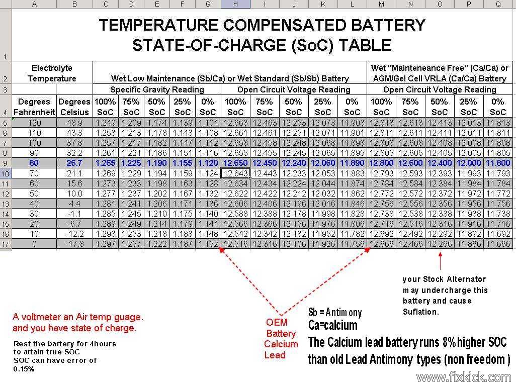
The reading will be 12.6vdc, at room temperatures. this means the battery is charged. If not , charge the battery .
If the battery is not charged or is not holding charge or is losing its charge over night , the starter will fail to start the car.
The voltage on the battery will tell you the state of the charge, by using this list. (this is very accurate)
There are a large number of battery failure mechanisms, open, shorted cells or just plain old worn out.
Test the battery or , barrow one to test the car.
The best way to test any battery is fully charge it, then load test it. All car stores can do this or use your own $20 load tester (sold in stores)
Testing a discharged battery will cause you to think it's bad and cost you $150 for that mistake, buy a battery charger and not a new battery first.
A discharged battery, might only be a lamp in the car left on, or the alternator is sick.
There are 2 simple tests for all this.
Charge it and see if the battery holds its charge for 24hours.?
if not , check for phantom drains. (a 5min test with any ammeter) If the battery self discharges, it's bad
if the altnernator don't put out 13.3v to 15vdc running engine over 800 RPM, the alternator is bad or it's connections are bad.
Barrow a battery from another car, before buying a new battery and save $150. (but for sure, batteries can do some very odd things..... no lie "the Usual Suspects")
For alternator issues, see my charge link above.
But you need to make sure the battery cables are clean and tight on all 4 ends. and that the Alternator Casing is well grounded.
PUMP: (fuel)
My next test is to check to see if the fuel pump has power, this is done with the meter set to 20vdc range and we then expect to see 12vdc at the pink wires in the left rear tail light housing.
Measure both wires to the pump , by placing meter leads at both of the 2 pins of said connector and checking voltage and each wire to body ground.
Pink wire to black wire must be 12vdc for 3 seconds each key on, (89/90') cars need to be cranked and some 96-98' 1.8L SPORTS.
The pink to body ground must be near 12vdc for 3 seconds.
The Black wire to car body must not exceed 0.5vdc or the body ground is bad. (behind the battery or a the pump ground point.
If the voltage is good at these points , and fuel pressure zero, then the pump is bad, pull the tank then pump.
MAIN power feeds. (Plus + power or Ground)
Rule 1 fix bad headlights first. they work , keys in pocket, so if real dim or out , fix the easy fix first.
All wires and ground connections are subject to the same rules for excessive voltage drop, I show this circuit (start) due to is easy ways to fail. (corrosion always wins here)
Any time any car has a loss of power, always check the head lights first.
IF the head lights don't work, we fix this first, because the head lamps are hot all the time and a power loss here, needs to be fixed first, as it is first in the chain of power; Battery and fender main fuse box)
The head lamps are hot at all times. (for your safety) Here is my page on that topic.
We connect the DMM on the 20vdc range and check power to the head lights. We expect 11.6v or more, 12vdc is typical. motor not running.
With motor running expect 14.7vdc (typical) 13.3 to 15v is range.
Stop engine.
Head lights are ON NOW ! (the HL switch is fully on) motor off.
I will call Head Lights the HL .
All tests are under full load, cranking ? or if HL has issues, HL on.
If the HL voltage is low (dim bulbs?) , check the voltage across the battery terminal lugs,. if the battery is below 12.6v ,the battery IS discharged (so charge it !) or the battery is bad .
(have the auto store test the battery) or alternator is bad (have it checked in same store).
- Phantom drains cause battery drain while sleeping or at work (8hr + shift)
- Battery dies, after a long drive, and HL are now dim and
will not crank over can be a bad Charging system (not just the
alternator)
If you take a dead battery to the AUTO store, it will test bad. Because you forgot to charge it first. (a battery is $125 a Charger is $10. your choice, your cash.)
If the voltage is good, at the battery , then measure the voltage from the battery minus terminal to the body metal, and the engine metal and the alternator casing.
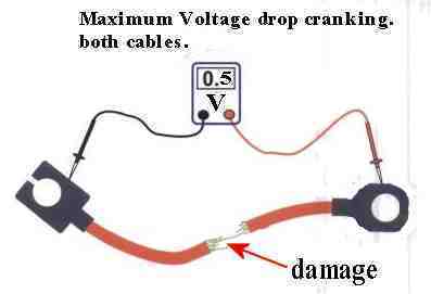
Meter set to 2-VDC range, all readings must be less than 0.5vdc, either HL on, or cranking, if greater correct the bad connections.
There are 2 tests here:
- meter touching only the battery Plus post and other lead,to the stater main huge solenoid terminal stud.
- meter touching only the battery Minus post and the other lead to the cars engine block (shinny metal is best)
Both tests cranking are less than 0.50 volts DC drop !
That was test 1 and 2.
We measured the ground voltage drops, under load, and will be very accurate, if the head lamps are glowing. (or at least turned on)
There are other tests to do that can cause, voltage drops besides battery cables,
Test 3: Is main power fuse power (voltage) battery is at 12.6v.
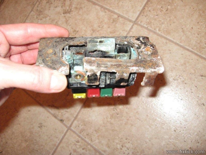
Next measure the voltage at all points on the fuse of the fuse block shown here , this is the main fuse block. All voltages (20vdc range) must be 12vdc or more. afadaf
Keep the meter lead minus, at battery minus terminal, for the above test.fda
Measure on both sides of each fuse installed on that FUSE block. Head lamps ON ! Test point "A" see power loss page here. or see charging loss here.
Expect at least 12 vDC there. It will read very close to 12.6v key off, not cranking
if the fuses drop below 11v cranking for 2 seconds. The battery has issues. (a tad lower in Siberia in winter)
If the 12v tests sag , or drop greatly , do a Voltage drop test.
If voltage is low?, do a voltage drop test from battery PLUS lug to Test point "A" , it must not be over 0.5vdc (2vdc range) or there is corrosion in the connections between the battery and this fuse block.
We now have full power to the fuse block and the head lamps are bright , if you have dim head lamps , see the link above for the head lamp circuits. Check for full 12vdc power to the lamps and that
The voltage on the ground side of the Headlamps is below 0.5vdc. (2vdc range) (both the 12vdc to lamps can be weak or the grounds bad to the lamp via the HL switch)
Do so, this voltage drop test at all fuses in the fender fuse box.
The large fuses in that box.. Make sure there is no drop there, caused by this.
Test 1 and 2: Details, Battery charged and good, Terminals CLEANED.
Repeat this test for both battery cables.
Checking cables (both) during cranking, meter on 2 Vdc range. (corrosion at any point here can cause starting failure)
With full power to MAIN box we next make sure full power reaches the sub panel. next.
The Sub panel is located just above your left knee seated in the drivers seat. Here is a typical view of it.
Some fuses are hot full time from the MAIN fender box fuse.
Others are KEY ON , hot only. (hot means 12vdc here) Hot is slang for this circuit is HOT or LIVE.
Use the voltmeter to check power at the input to each fuse and output (both sides). Expect 12vdc to prevail hot full time or KEY on , as appropriate.
See here, this link for which fuses are hot and when they are not, called POWER Distribution schematics.
If the fuse output is not 12vdc, the fuse is blown. (it must be the same reading on both sides of the fuse) like this example: 12.01 and 12.04 volts, near same, and good. 12v and 1v is bad. 12v and 0v is bad.
The cover for the below block, looks like THIS., up to 1995
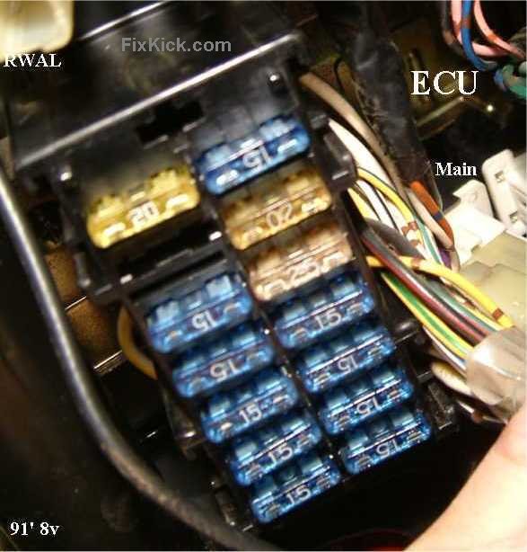
You can check both sides of each fuse hot by back-probing techniques.
Zero volts on one side and 12vdc on the other , shows a bad fuse. (some fuses look good but are NOT)
EACH fuse must have 12vdc on each side, key on.
Resistance? , Ohm'ing stuff out. ( make sure there is no power applied to the object under test, when measuring resistance)
Rule one, the battery neg. lug is the car, must be disconnected to check ohms of any circuit in the car or the meter will LIE to you. The Resistance scales of the meter, have zero tolerance for live circuits.
The purpose of the wiring is to deliver full power to all electrical items on the car , or to connect, and read sensors.
Resistance in wire or connections and switches , will cause malfunctions. (cause by corrosion , breakage or weak crimps of terminations.)
The connectors must have no more than 0.1 ohms resistance.,
A Fluke meter or any DMM, can do these tests easy.
I always use volts to test fuses, live , in the car with the key on.
The fuse ohms test does work too. (removed from car)
First take out a fuse. now put the meter on Rx1 scale (mine has Rx2). (or the lowest resistance range)
Now using the meter , short the 2 test leads together.
The meter will read 0.0 Ω ohms that is a short. read the meters manual to see how to get a good low ohm reading. Not 0.5 k or 0.4 meg. but Ω, set the DMM to beep mode and hear it beep for 0 ohms.
0.2 Ω , is ok too, better meters can auto zero calibrate, this small error, do so.
Next, connect the fuse under test, to these same 2 meter test leads.
It will read 0.1ohms Ω max (on $3 meter like the top of this page it may read 0.5 ohms) , but will read the same with shorted leads. so that is no surprise.
This works for wires, connectors , switch and fuses. all must read a perfect short. (switches closed)
Keep in mind, the best test for any connection is under actual car DC power, using VOLTAGE DROP tests. Things can fail, under full current loads that most ohm meters can never find.
You can calculate resistance doing a voltage drop test , mentioned above and using the below OHM's law wheel.
Lets pretend the voltage drop from the battery to fuse panel main is 1vdc. (bad) done above ! With just the head lamps on.
What is the resistance. of the feed.?
Easy. Most young men/ladies, today had new math in school and can do simple Algebra.
R= V/I (in Algebra'ese? this states, resistance equals Voltage divided by Current.) {ohms laws}
R = 1/ 10 amps ( head lamp current)
R = 0.1 Ohms.
The total power used by the head lamps is. 10a x 12v or 120 watts, key off.
Current tests: Using a typical Serial shunt Amp. meter.
Measuring current is the most difficult. ( advanced training ) USING THE OLD SCHOOL serial Ammeter seen at the top of this page.
But is not difficult , if you have a current clamp meter. (as shown below)
Serial meters :, like the 1st two shown above. (no clamp)
Serial Rules:
- Always start on the highest Amps range and work down. (and use a series resistance when measuring wires for shorts to power feeds , in live circuits)
- Never place an ammeter across any power source, in the old days ,the meter exploded (Simpson 260) ,today the fuse blows inside the meter, making everyone think ,every measurement is zero amps.
- Always put the Ammeter in series with the load. (never ever across any battery or power pack,or charger, etc.)
- Use a test resistor to prove the meter can actually read Low Amps, I use a 100 ohm 2 watt resistor ( brown black brown) in series with the meter and the car battery. I see 0.12 amps flowing. Meter works.
- Always test the serial amps first. use a 12 ohm (15w) resistor in series with the meter (20 range) and read 1 amp. (a technician ALWAYS keeps tests resistors in his tool box, for testing reasons)
- Never assume that if one range on the meter works , that all do, test it , find the truth, ( the #1 reason for new users to mess up)
Try the AMP CLAMP meter, it is 10 times more user friendly.
Rule 7, insert the loop clamp onto only 1 conductor at a time, never a pair. Bingo the current flowing is displayed. (and even shows direction with the plus and minus LCD symbol)
This meter can also show the direction of current, and this can help you find which end of a wire, has a short to 12vdc or ground, by flipping tool over....(RTM read the meter manual)
Set set dial to current max (rule 1) and then reduce the dial from max current to less. for best accuracy.
The amp clamp run down a harness and you discover the current drops to 0 mid span and past here, that is a short to ground, or there are no loads past this point. (having an FSM showing all loads and branch points, helps you greatly here)
The AMP CLAMP: (this one below is discounted, Sears sells one for $89 and is worth every penny)
Tenma P/N :
72-7224
Do not buy any AC amp only meter, only the AC/DC meters work in a car. or DC only !.. DC costs MORE ! Most Amp Clamp meters sold do NOT DO D.C!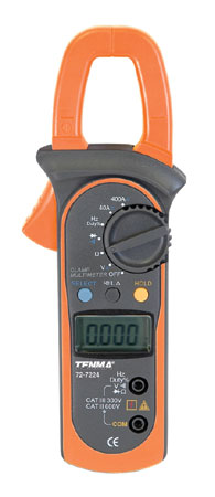
As sold by MCM electronics , a great deal. Measures DC amps (with clamp) , most cheap meters DO NOT do that. About $55 above. (some times on sale , at ebay)
I call it my AMP CLAMP !
How to use it?
I can connect this amp clamp on either battery cable and measure ALTERNATOR charge rates 50A, or starter current.100A
It can measure currents from 0.1 amp to 400 Amps.
If you are blowing the FI fuse in the car, this tool can find the overloaded wire and its faulty load, easy.
Connect this meter to the battery cable , and turn EVERTHING off on car , key off, Headlamps. The current must never exceed 0.045 amps. (ASE /SAE spec)
See Phantom battery drain tests here.
If it does exceed this leakage rate, you have dark current. See my electrical fail page for help.
This meter below, is hard to find, it can be had for $40 or less or find one on ebay, they are getting rare but are TOPS in usefulness. (small and rugged)
The Hoyt SG-1 (magnetic meter, has no wires at all) See the 30 Amp weaker cousin here.
The one weakness in this meter is it can not resolve drains (or loads), below 3 amps. (it has 2 ranges one for starter and one for Alternator)

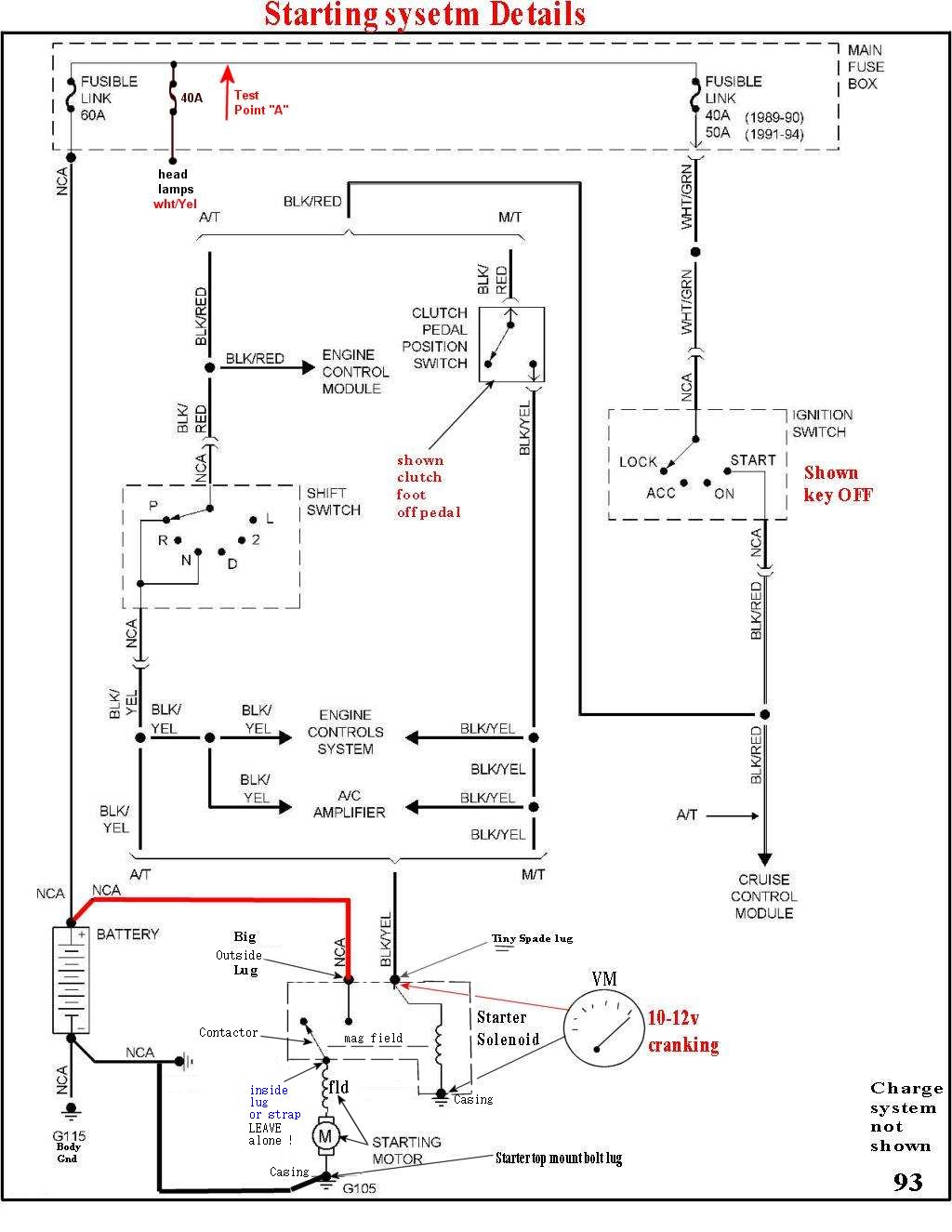
Test point A: Fender main fuse box.
Below: On newer cars there are more fuses, Check for voltage drops on ALL fuses in them box, not just Test Point A.
The drawing below only shows those things needed to CRANK the engine over.
Rule 1, the SOLENOID goes dead, below 8v, to keep the pinion gear for ripping the ring gear to hell.$$$
So ,when you hear just a click, that is Mr Solenoid yelling (too low voltage bud !)
 either HL on, or cranking,n
G105 , loves to fail , due to last mechanic not tighting it to spec, after working on it. It mounts to the Starter top or bottom bolt, no where else allowed.
NCA means, no color assigned. (Suzuki lingo)
Revision level 5 ++++ 2-24-2014