
Dah factors:
All fuse in the right fender box must be good. (look good and measure zero Ohms) Some look good and are NOT.
Did you try a new or known good battery first? if not why not? Barrow one from friends, etc.
and if load testing a battery? , did you charge it first, if not, good batteries fail.
Do not load test , non fully charged batteries.
Unless you like wasting $100 for nothing. (plus labor)
Do not run the Car with the battery cables REMOVED! or risk blowing up all lamps and Electronics. (this is old school ignorant) STOP !
Facts: The Charging system (Alternator /Generator) powers all electrical loads, running, and keeps the battery charged.
The Battery only supplies power to the car, when not running or starting, or at Alternator failure.
The Alternator grounds, must be perfect or the Alternator will not operate correctly. (the regulator inside gets confused)
Keep in mind, there are only 3 basic failures, here, in the macro, battery , alternator and the wires. (at full RPM) Battery is always 1st.
Most what you see here , is for old rusty corroded cars, new cars with out this damage , are easy to repair.
I have the Full FSM , tests below , translated to Gringo English, from Japanese English, And my own special tests at the end.
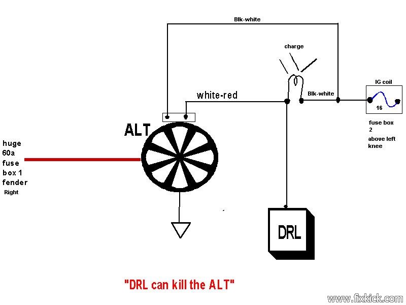
This page covers the odd things too, and the rare , like DRL failures. (DRL modules love to burn up ,then mess up our Field pin)
You are here because the battery keeps discharging and not because power from the battery is failing to reach the fuse panels.
You have already tried another known good test battery and it's not the battery (a #1 top failure item) sorry for repeats, but why skip the first step. ?
And that you battery is not draining over night due to Phantom Drains , aka. Dark Current.
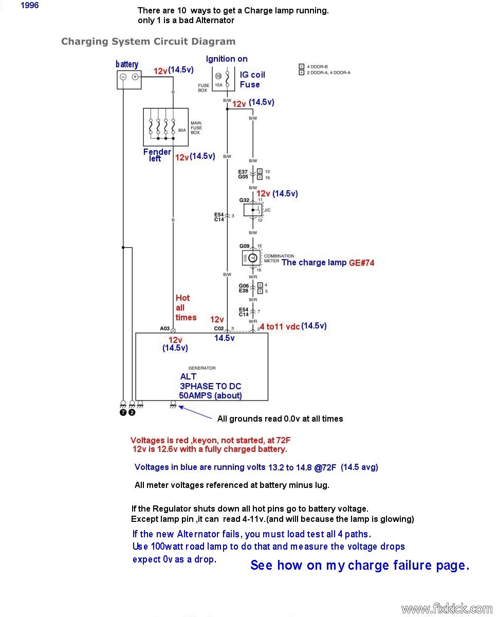
You are here, because the charge lamp, came on running. It can for 10 reasons (including belt fell off)
You are here, most likely after finding car battery will not charge and that new battery, didn't fix the charging problem. (3rd repeat ,sorry)
The DRL module (Daylight Running Lights) can kill the ALTernator (makes a good ALT fail) how , 96' USA, car example?
If you have replaced the Alternator 5 times, (over 2 is enough) then your wiring is bad. (see above link) or do the full load tests.
Warnings, the battery can explode ,rupture , leak acid rapidly, if not careful,
Never disconnect the Plus (red) terminal of the battery first , (Pull the MINUS first) or risk shorting battery and subsequent acid bath., or worse , blindness.
Never disconnect the battery or alternator or related fuses, while engine is running or starting , or you may blow up expensive electronics components, (ECU?) 2nd repeat.
Never cross over the battery plus terminal to the car body or risk violent battery rupture and acid expulsions. ( extreme danger ) Same goes with JUMPER CABLES.
Never work near any lead acid battery with out proper PPE. "Personal Protection Equipment" Eg: Goggles , gloves. rated for chem.'s.
Never remove the alternator or fuse boxes with out FIRST disconnecting the battery minus (-) terminal. (2nd repeat , sorry but watched so many work mates, get hurt)
My page and journal, is only best read after , a real FSM (factory service manual) and chapter 6D3 in the GM/GEO FSM. (read the safety issues.)
See Chapter 6D in the GEO FSM ( GM) , read the 1996 charging section and safety issues.
The Alternator on this car, is a 4 wire alternator , 3 lugs and ground, and that ground connection is very important) None are optional.
Tools: At least a DMM, and better is the AmpClamp seen here. (the passive Ammeter tool, I clamp onto the wire, and the Current, Amperes are measured)
Optional: A battery charger, jumper cables, and a spare good battery from wifes or friends car (4th repeat), an optical tachometer (hand held)
Alternators are complex, in some odd ways, This link exposes this great complexity and huge list of failure modes.
Test #1: (with your DMM tool, at least.)
Start the engine, make sure Dash RPM is 800 minimum, and alternator belt DOES NOT SLIP.
The Alternator can shut down, and 2 pins on the Alternator, will measure at battery voltage (12.volts) the ALT, lamp pin will be less, as it glows the dash lamp.
A dead Alternator will look like this... You will see only battery voltage , in fact only the STATE of Charge of said battery, 11 to 12.6v.
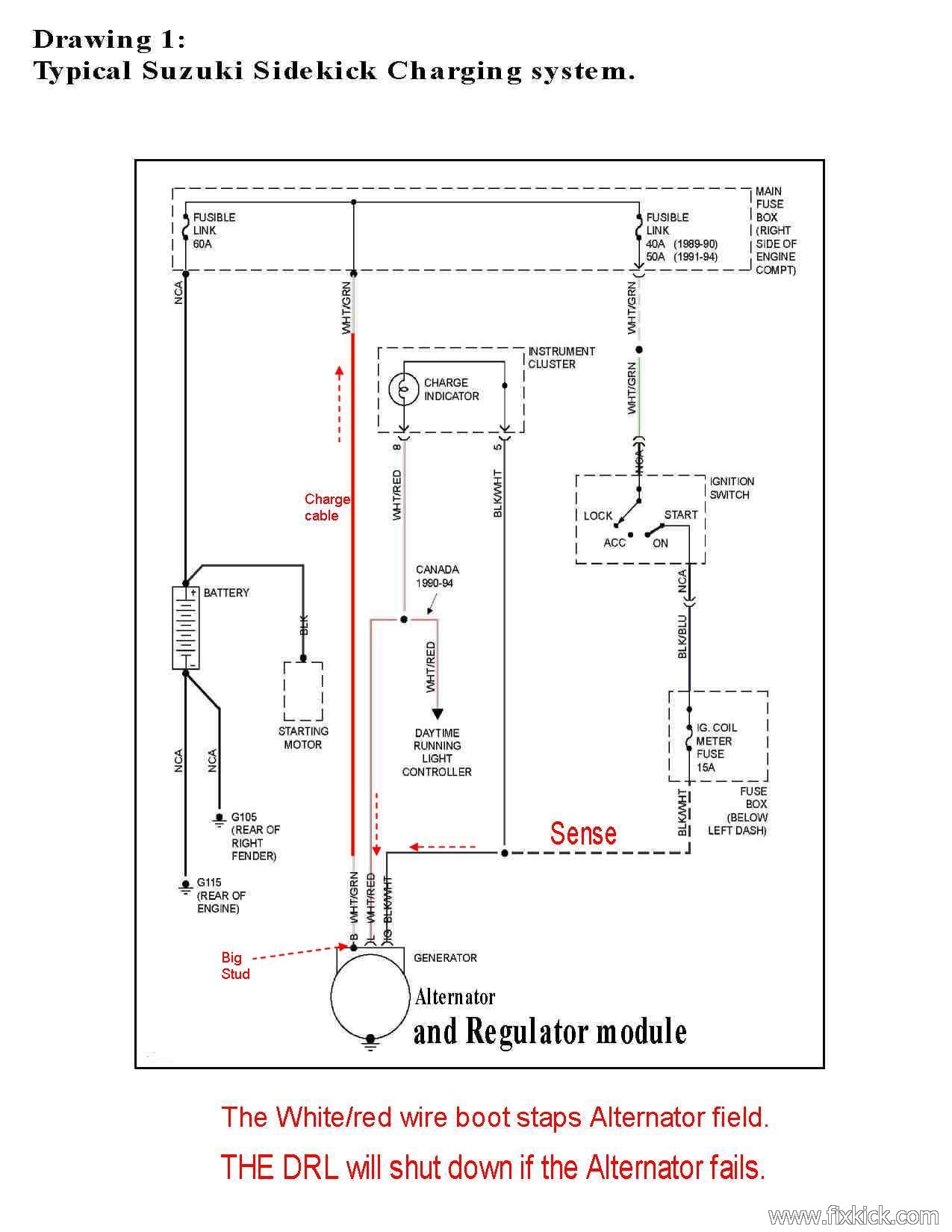
12v at the ALT big lug, 12v on black-white Sense pin, 0v on ground and way less voltage on the white-red pin DF+ field pin. 5v to 10 v (the lamp resistance cusses this drop)
This is the sure sign of a dead ALT or that the Regulator inside saw an error at startup and shut the ALternator DOWN.
Why would it do that, well, to prevent blowing up the $1500 ECU and $1000 head end Audio system, comes to mind.
If the Regulator is happy the Big ALT PIN/lug goes to near 14.7vdc, and stays there at all times. (some newer ALTS can drop down to 13.5v float, with full battery charge)
This one fact makes alternator testing very hard, due to the Regulator inside, hiding the evidence. (born dead)
(that is, the alternator was born dead,it did not come on line, as the engine started)
You start the engine and you don't get 14.5 volts , but only get 12.6v or less across the battery terminals, the alternator is not working!
If the alternator is born dead, you have no alternator current and can not measure that , nor measure what caused this failure, a VOLTAGE DROP.
The regulator can in fact, drop the Alternator OFF LINE. (I call this born dead)
Born dead means , at startup and boot up, the regulator shuts down. The Alternator can produce Illegal voltages.
Voltage Drop is resistance in the Charge system, all 4 wires that comprise this system. must be clean good , tight and resistance free.
The Engine never idles below 800 RPM, so the Alternator is happy and the Alternator pulley spins at full normal RPM and does not slip.
One can force the regulator to wake up, by full fielding it. (for short times) and measure every wire related to this system for excessive voltage drop.
When full fielding , make sure the voltage across the battery does not exceed 16v or your cars electronics may get unhappy.
One way to avoid this Field test, is to get the alternator tested at (brick auto store...) now you know it good an that the cars wiring is bad.
Repair the wiring and bingo.
Here are some bench marks. (crude): What to expect.
The basic spec. voltage drop for this cars copper wires is about 0.1v (1/10 volt DC) max. (not cranking that is different and 10x more current)
If you Alternator is producing current, into the cars full load, you can measure voltage drops, now. (the accessories on , the more load and more potential drop)
Volts = Current times Resistance, E =I x R. if current is near zero , you can not measure the drop voltage)
The head lamps draw (suck) about 10amps , the fan about 15amps on high, the rear defroster, 15amps. Use these loads to test your alternator.
If the Alternator goes off line, these tests are useless, (battery is running things now). Monitor Alternator voltage first. (above 13.5v) or a wasted test.
When the engine is running with no Accessories on at all, the alternator (charged battery) current is about 5-10amps, (no accessories on at all)
Figure max 4 amps for the ECU and sensors/injectors/actuators, and 4 amps for the Fuel pump inside the tank. (8 amps ball park amps)
Bad fuel pumps love to go to 10amps, even causing ECU reboots, measure the pump at the PINK wire, in the left rear tail light cavity. 4 amps.
The faster the RPM the more current due to injector duty cycle.
Where would you measure that ALT current?, answer, at the big charge wire bolted to the Alternator stud or at the fender fuse box.(same wire)
As you turn on accessories, this wire current can rise , and stop at 50amps, with everything turned on and a discharged , charging battery.
You can hit 25amps easy. with all things turned on.
If the ALT amps are near zero Amp's , the ALT is OFF LINE.
Not inspecting the charge path wiring end to end, can result in many new alternators installed for nothing. This page show how the alternator fails too.
If you have the DRL option, remove the DRL module now. (look for burn marks on the DRL connector (bingo?) 1996 and newer USA or older in Canada.
My list of all alternator failures. The ALT, or GEN.
- The Alternator belt must be as
spec. tension and running about 2 + times engine speed. (note
large crank pulley and tiny alternator pulley (calculate ratio?)
- Clean both battery terminal and lugs. (at all 4 ends is best)
- Try a known good battery
(barrow one) (to test your battery, first charge it first, then test it or the test will fail )
- The grounds are good in the engine bay, seen here .
- The alternator case must
be grounded to the engine block. (cars that run in the
Salt belt fail this easy , power side and ground side)
- Alternator case
grounded, mounts and all engine grounds and the battery largest Minus
cable does mount to the top starter mount bolt, if not , FAIL.
- The power
distribution failure , between the Battery
and Alternator. This is very common on 20 year old cars... check it out.
- The alternator will not
charge the good but low battery ? , and the dash charge lamp glows running. replace the
alternator. (above good)
- Take the ALT ,to ANY AUTO store for a test .I
think the tester is 100% valid, and for sure you watching !. A
FREE TEST ! Trust it !
- The alternator will not charge the battery and the dash charge lamp fails to glow, replace the lamp, the alternator can fail, with a burned out lamp.
- All the above checks out,
do the 3 factory tests.
- The full Fielding test my be possible. (risky) The auto store test does this, in step 9.
- All
the above checks out , one more test to see if the Alternator can be woken from the dead.
Do not ever replace the dash charge lamp with any LED, or the Alternator will fail. The lamp must be correct type. GE #75 (all but CEL/SES lamp which is #18)
Keep in mind, at all time, that a dead battery can be caused by dirty terminal's.
Clean both battery post terminals with this cheap tool.
Use the red colored anti-corrosion compound or paste on the lugs.
 The battery term. cleaning
brush, every 6 months.
The battery term. cleaning
brush, every 6 months.Theory of Operation: (The alternator can fail in many ways, even excessive noise (audible) or electrical noise).
No charge, over charging, dead, or under capacity (not reaching 50amp spec.)
It can also fail and go OVER VOLTAGE.
This system is very simple and consists of just a few parts. (but is complex, read this link and you will agree)
Some charging parts, are also part of the starting system. (battery cables and the battery, is 2 examples)
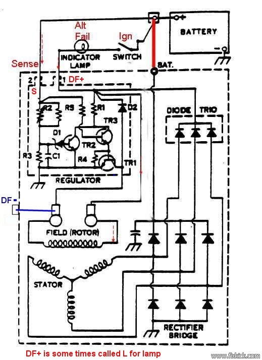
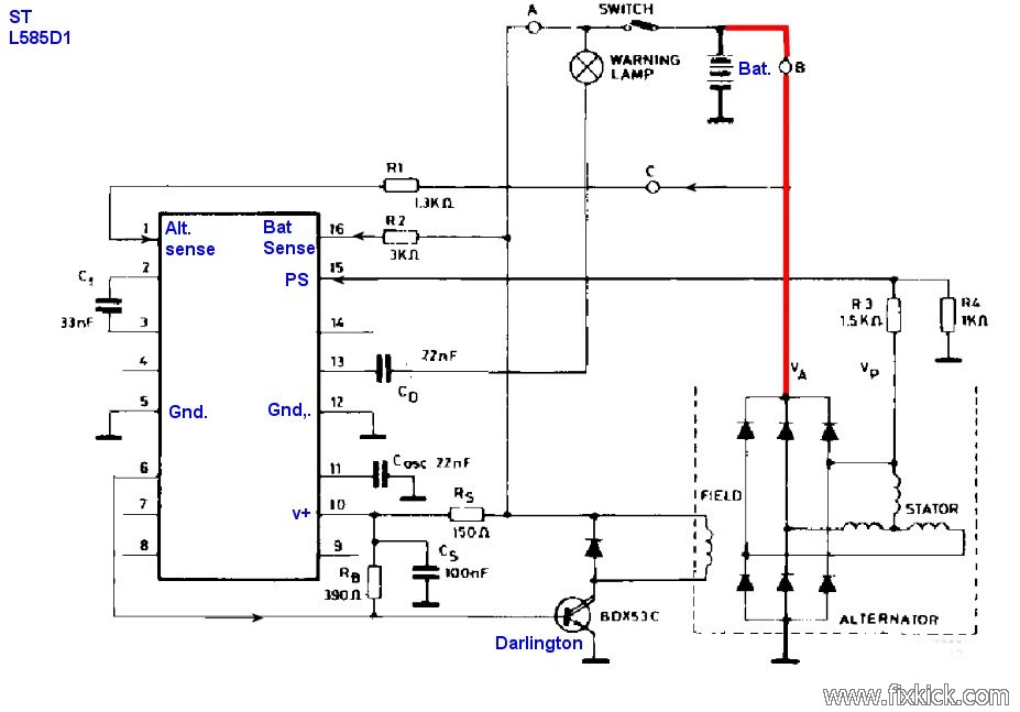
The below drawing #1 shows the basic system and newer cars , it has changed little over many years.
The system while simple, but can fail in many ways. Including a slipping or missing drive belt. Yes, they do fall off. Or stripped out main crank pulley!
The alternator has a 3 phase A.C. Generator at its heart and if one Phase fails (bad diodes) the output can drop by 1/3 or 33%.
These same diodes can short and cause the Alternator to be a huge noise generator , causing ECU malfunctions (rebooting it over and over. Crazy ECU !).
The Stock Alternator produces 55 amps max. of output, at cruise. ( less at idle, but will charge battery at idle with little effort) Current capacity varies by RPM.
This same Alternator has an internal voltage and current regulator, that can malfunction. ( in many ways and is complex how it works)
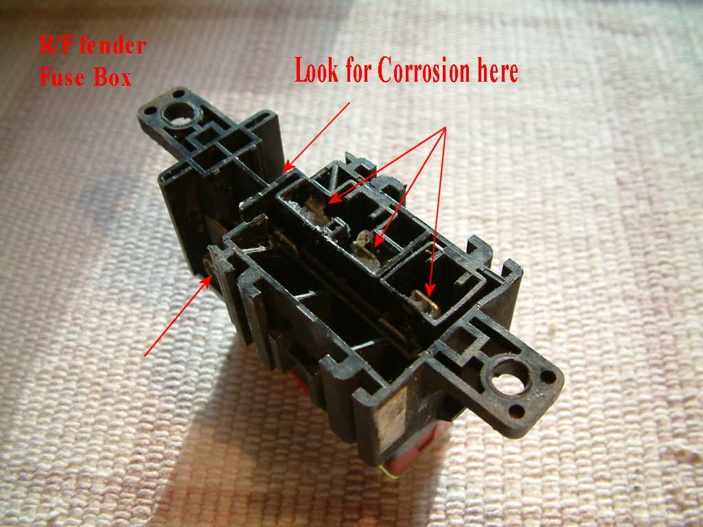
The Alternator fuses below, are located on the right top fender Fuse block, it loves to corrode and fail (lift the fuse block and look !)
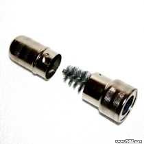
See Quick Disconnects under there, fail?, common in rust belt locations).
It should go with out saying that the battery , cables and all wiring below must be good and clean and no corrosion. Clean the terminals on the battery.
It the regulator sees too much line resistance , the regulator may overcharge the battery and damage the battery .
There are 3 basic tests.
Check the battery State Of Charge. (called SOC) "Is my battery charged?" or NOT?
You need just a good hand held cheap digital voltmeter, to do these tests.
This weak meter is good for trunk usage only"$4 meter sold at Harbor Freight"Good only when Desperate or stranded
I'd never use that $4 meter, I use at least a $15 Walmart(®) meter , (my meter is about $100)
The Amp clamp meter is the prefect tool, (low clost) to diagnose any car, or vehicle. (passive current measurement is a god send)
The rested battery must measure about, 12.6 vdc at room temperature. ( engine and KEY off ) Set meter to 20VDC range and touch the 2 battery terminals.
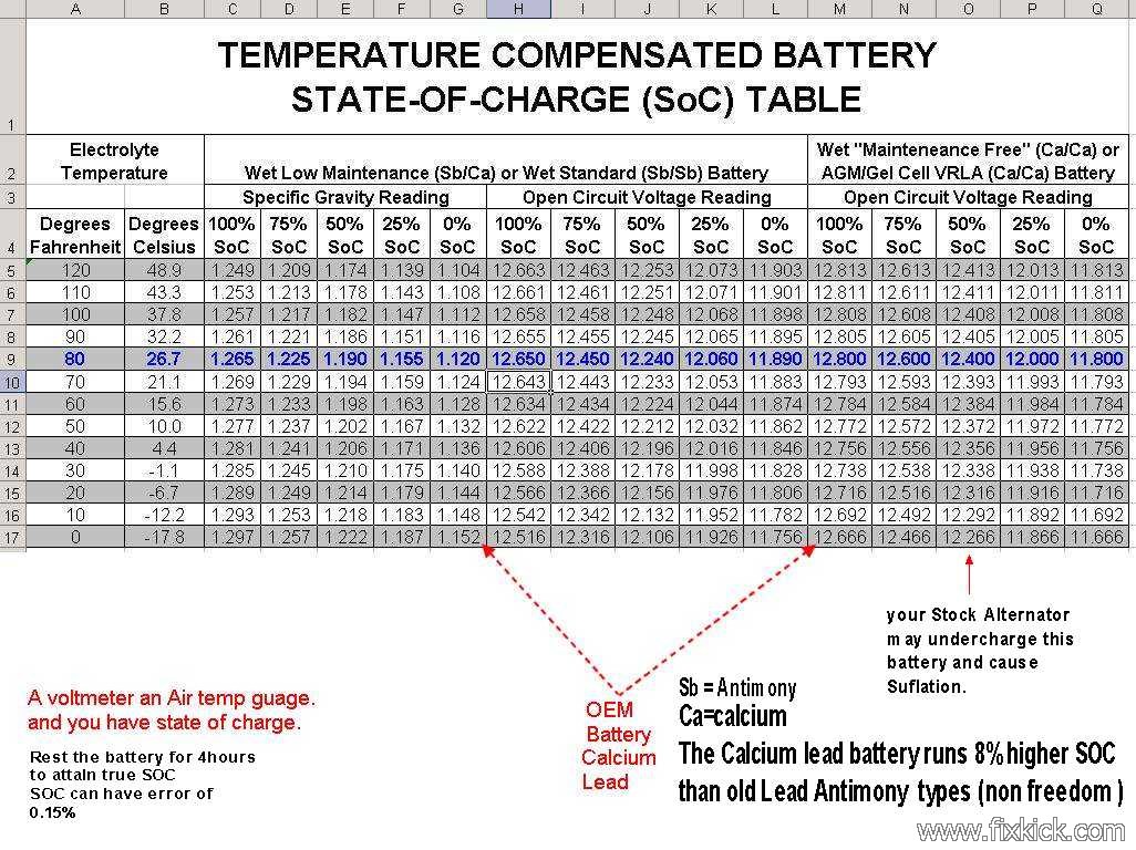
This voltage is for room temp. please adjust all voltages using the charts I have provided, for temperature corrections.
A 4 hour rested battery is free of any surface charge errors.
STATE of CHARGE battery: (please keep in mind bad batteries, can read with perfect voltage) All voltages here are normal room temps.
Imagine the battery shrunk to a 1 inch cube. (age caused) The plates inide, can erode to that equivalence after long time usage, and read 12.6v)
Here is my SOC chart for temperature compensation. in EXCEL format, or here as JPG photo. As you can see ambient temperatures effect the readings.
This is the state of charge, with this table, you can determine how much (%) a battery is charged.
Look at the 100% columns, use the left column for Sb/Ca cells. See the 12.65v ? 12.5v will start a car. See OEM readings in the center.
This is what you should read .with any voltmeter , across the actual battery terminals, at rest 4hours minimum and at standard Temperatures.
If the voltage is low , the battery is discharged, so charge it up. and continue troubleshooting.
If the battery is good and charges up to 12.65 it may be good, but bad batteries can in fact fully charge up and have weak power.
Batteries fail in many ways. (open cells , shorted cells, and just old and weak).
You can take you battery or alternator to any "AUTO "store and they will test it for free. If all this is confusing.
You next want to find out, who or what is discharging your battery , a malfunctioning Alternator ( keep in mind good ALTs can malfunction !) or a parasitic drain.
If a charged battery drains overnight then you have a parasitic drain. jump to that page now .
All tests require tools, a voltmeter and a battery charger. ( are the minimum , and inline inductive D.C. ammeter is really nice to have, too)
The below tests require a good battery and good cables and good connections.
There are At least 5 on car tests: (in the Macro form) ( I will not show the 6 or 7th , Google Alternator noise or low power)
- Is the Alternator dead or alive test. test 1.?
- Is my regulator alive Test 2?
- Will the Alternator portion (regulator bypassed) charge the battery?
- Basic voltage tests, and inspections.
- Full load testing the 2 big , 50amp
charge paths for weaknesses.
A 7th test, is using a scope to see if the diodes are shorted and making tons of electrical noise. (Alternator will sing too (audibly)
A simple Amp clamp Ammeter can be used, on the big (6 gage?) Alternator wire and check for full 50amps power. by adding the same to all accessory loads.
Alternator Test #1: Factory FSM tests, chapter 6D3 page 1-11 (when you see J39200 that means any DMM)
- Turn on head lights for 2
minutes. ( engine off, we
are draining battery here , just a little, so the Alternator can see
that drain and start a full fast charge.)
- Start engine. (read my FSM link above for all the details of this , this section is a summary !)
- Measure battery voltage.
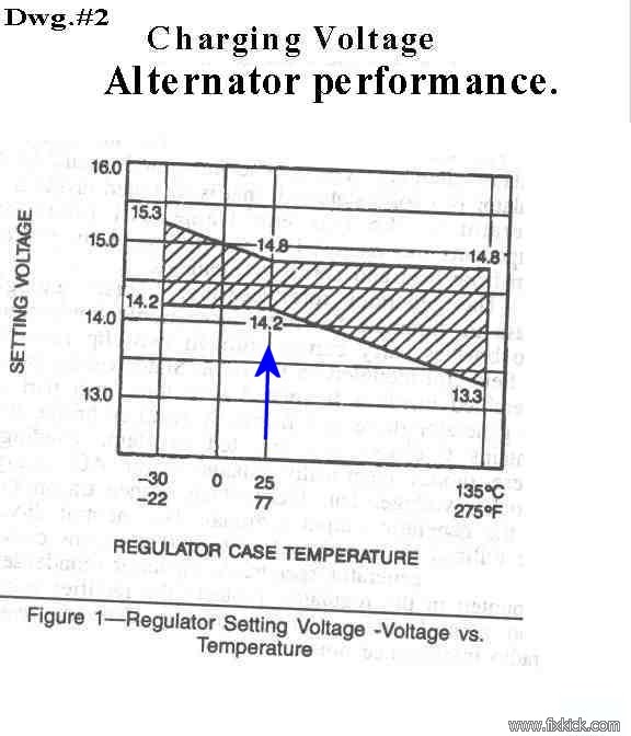
- The voltage must be 14.2vdc minimum see Dwg #2 below. 14.5v is typical at normal out door temperatures. mine reads 14.7. ( you must discharge battery, a little first)
- If this test fails repeat all 4 steps 1 more time.
(or increase head lamp on time to 5 minutes,
motor off)
- A failure here can still be a bad battery , or connections. Just because the alternator is not charging , DON'T MAKE IT BAD !
the risks of accidental running ,with an open circuit and subsequent over voltage conditions (blowing up ECU or expensive audio equipment is no fun day_
Alternator test 2: (FSM page 6D3 page 2 step 6)
Voltage regulator test. This test is to see if you can wake up the voltage regulator, it it can not be woke up, the Reg is bad or you have corroded wires.
- Connect a variable output type battery charger to the battery posts, observe correct polarity. red to red, black to black. Plus to Plus.
- Connect your accurate voltmeter to the same points. A DVM/DMM is best.
- Key on , no start.
(the Charge lamp must glow, due to
Alternator not spinning , this lamp going is the Regulator Actions)
- While watching the dash Charge lamp, increase charger voltage until the the dash charge lamp begins to dim.
- It must dim from 13.5 to 16v,
if not the regulator in the
alternator is bad. (or bad wiring / connections ) (I'd say
out at 13v (about)
At great risk to the cars electrics and ECU. (over voltage ! and over charging)
I show this test only for completeness, and is common practice on other cars....
I don't like showing this test, as this requires , fully activating the Field minus terminal and then you need for a 100 amp , Ammeter test tool. (reads 50amp)
Goes to 50 amps and over 16 vdc easy.
Some versions of our alternator have a DF- pin, (see drawing 3 below) this pin runs 4v-11v in good SYSTEM.
Some alternators have special extra pin on the rear of the alternator to cause full fielding.
This pin is the Field minus pin, if grounded by YOU, this gates the field full on, and full charging, and by passes the Regulator.
If you ground the wrong pin , you blow fuses. The correct pin is not the 2 wired pins but the unwired pin.
Key on, no start.
If paranoid (I am) then connect an old head lamp from this pin to ground and see a huge voltage difference between DF- and the 12v pin 1. Blk-White.
If you see 12.6 on pin 1 and 11 volts on the hopeful DF- pin then this is the DF- pin. (using the LAMP as a load)
Let me be clear, all car wires are normal in the charge system, im just grouding one pin, using a starter remote start button here to do that, is spiffy!
Start the engine.
Ground DF - (minus) and messure the charge cable Amps and battery Volts for a minute or two, no longer, as this is a full tilt test.
If you get over 13.1v (16v is common) and see 50amps flow the Alternator (sans regulator) is GOOD. If not?, bad ALT or bad wiring.
This test, only proves the Alternator portion is alive. Nothing more. Not the Regulator, and will ignore much bad Charge system wiring, unlike your regulator.
Warning:
If you ground the wrong terminals of our alernatoActual internal Alternator failure mechanism's and symptoms: A hit list:
- Bearings bad or seizing (a squealing fan belt?, noise from bearing , yelling to you, I'M BAD !)
- Brushes bad ,worn to nubs or gone , (weak or dead alternator or intermittent op.'s).
- Rotor coil open or shorted , (weak or dead alternator or intermittent op.'s). open coil ,kills Alternator dead as a door nail.(a Roman refr)
- Stator coils open or shorted , (weak or dead alternator or intermittent op.'s). and EMI noise (elect. noise, heard on AM radio?) For sure with a SCOPE.
- Bad bridge, opens or shorted ( (weak or dead alternator or intermittent op.'s). and lots of noise if shorted, EMI will happen (Electronic -Magnetic Interference)
- Bad diode trio, opens and shorts, (weak or dead alternator or intermittent op.'s). the regulator goes quite nuts.
- Bad regulator, (this can be bad, in many ways, causing a vast array of complex or odd and intermittent symptoms or just kills Alternator dead. and Dash lamp odd indications.)
- Rusty grounds, on case and all the way back to the battery , can kill a good alternator (only causes a good ALT to misbehave)
- A Bad rear connector or bad dash lamp, to same, or any of it's wires not conducting or grounding out.
Hint, Avoid China made clone Regulators like the Plague. ( or the whole thing for that matter). Buying no name parts, is a mine field of grief.r, you blow fuses or blow the regulator up. (or damage the Alternators diode pack)
Ok, you took your Alternator to AutoZone 5 times and bought 3 new ones and it still wont charge your battery.
(could it be, the battery might be bad? or wires and connections? yes, sure , and IS !)
TEST 3: I jumper in, my test lamp from the battery Plus post to the White-red W/R wire on the Alternator , running, to see if I can wake up my regulator.
This proves the lamp is bad in some way, if this test passes.(wrong or bad lamp or wires to same in dash cluster)
I do this and the battery plus terminal goes from 12.5 to 14.7v, I just woke up the Regulator by actions of test 3.
Test 4: (simple voltage tests and inspections of the 4 wire paths)
Tests for wiring: (voltage drop tests) [ use drawing below for a reference ] This can pass and still be bad , due to the regulator shutting down.
It is impossible to find a bad connection (voltage drop test) if no current is flowing, (as in the case of regulator shut down)
All fuses in CAB and Fender fuse box, test good with an Ohm meter (less than 0.5 ohms , measured , zero is perfect if meter autozero's or you do that. )
- Key on ignition, no start, the Charge lamp must be on, if not, it is bad or the wires to it are bad. (or bad alternator regulator ){ correct this first}
- Start engine
the above light may come on
, after all, the charge system is failing. (yes?, well lets fix
it )
- Set
DVM to 2 vdc or lowest scale DC. "DROP tests" (read you
manual for auto ranging meters, I recommend non auto ranging for
NOOBs)
- Place the black lead of the meter to the battery minus terminal (all were cleaned right?)
- Place the red
lead to the body of car. Measure < 0.5v, if this
fails battery grounds are bad.
"<" means less than.
- Move the red lead to the
alternator body casing, expect the
same if you as above, read above 0.5vdc the Alternator mounts are
corroded. correct this now.
- Move the Black lead to the Plus terminal of the battery, and the red lead to the B terminal of the Alternator (large Alt output, lug stud, on Alternator rear).
- The reading must be < 0.5vdc. if not this wire
cable is bad. or that 60amp fuse box is corroded. (or connections
"Spade type fast off on connectors").
- Move the negative
lead of volt meter to the Minus
battery
terminal again, and set the meter to 20 vdc range.
- Next put the red lead on to the Black/white wire of the Alternator, it must read 12.5 to 14.8vdc , if not the ignition wire feed is bad. (this wire).
- The above step, the reading must be the same as the voltage
at the battery posts ! Actual. The correct reading should be
14.2-14.8v (charging)
- If all the above checks out ok, then the alternator is bad.
- The connections can be bad , close examination will show the truth of this.
- The Large Battery cables must be clean and tight at all 4 ends, The top starter bolt is the Battery Minus cable and must be attached.
- The Alternator casing must be cleanly attached to all mounts and all mounts cleanly attached to the engine block or the Alternator WILL FAIL to operate
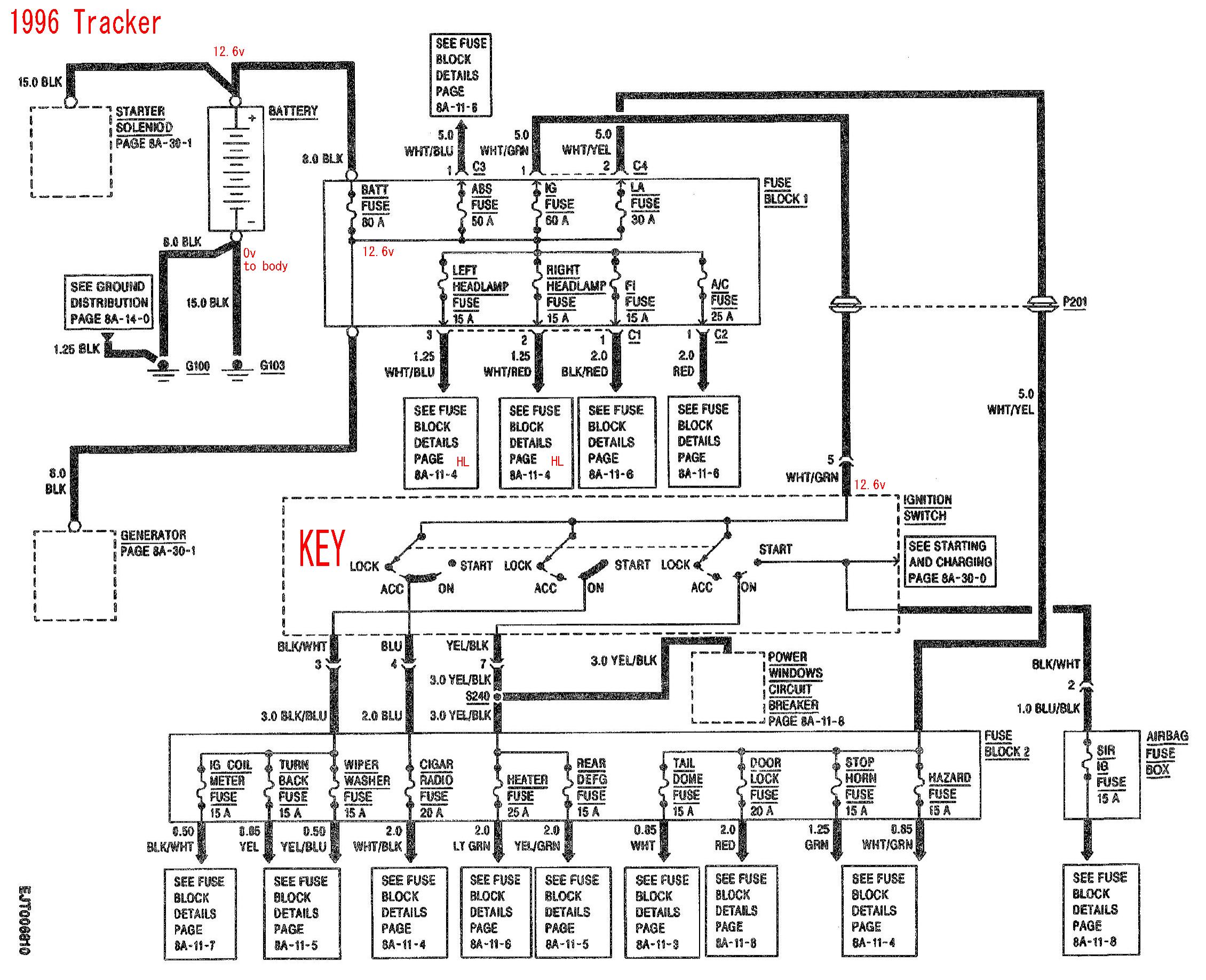
This is real Suzuki wiring , the alternator will fail with a bad battery or wiring or even the fuse blown on left below (kills all DC power in car too)
1996 main box is vastly changed, see it here: See 1998 here.
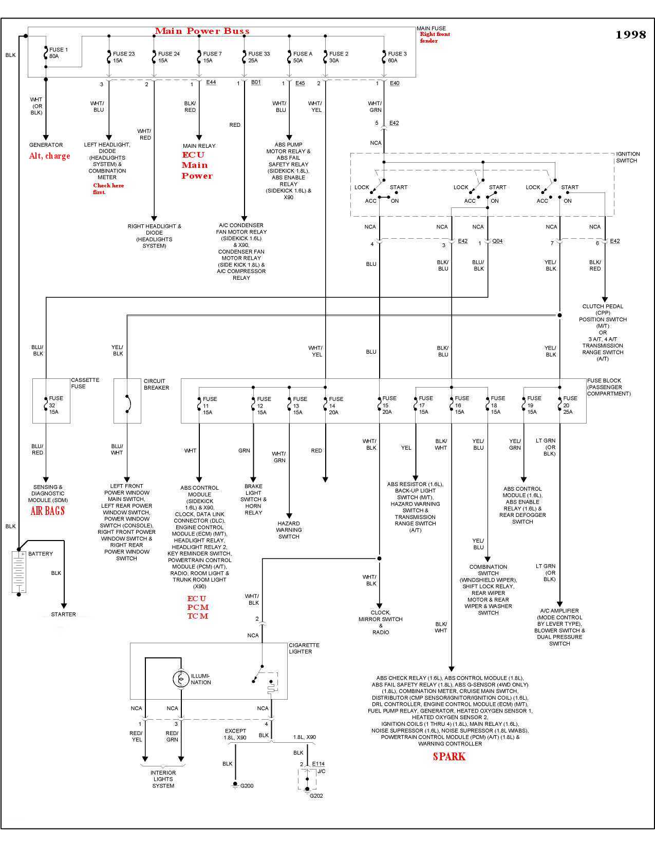
Below is 1989.
Or conversely, the defective ,DRL can kill the Alternator (not hurt it) just interfere with the regulator in a vary bad way.
The Below chart, shows how the charging system behaves at different temperatures.
And the natural variance from 1 Alternator to another ,both good .
At room temp.' the voltage should be 14.2 to 14.8 volts D.C. while charging.
( it's your job to set the stage and start with slightly discharged good battery before this test )
My 14.2 is the low good side, for any alternator at room temperature 25C . to minus 30C.
The gray area is the uncertainty region , varies by brand or maker or part to part.
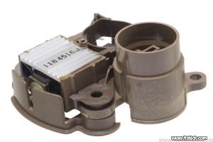
The Actual 1995 Sidekick REGulator module , removed , Below: 32500-60A10
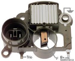
The alternator internals.( a typical generic example) The extra conn. pin is DF (-) minus, I think.
The best page on alternators and regulators, I've ever seen, is here on this page .
Self Excitation : (keep in mind, self excition with no battery is a recipe to blow up lots of electronics in the car)
Is the ability, to generate power with no battery, from zero rpm. (it can be random !)
Imagine the Alternator, used as a wind generator. ? and no batteries across it; many will not self start up. (born dead)
Most Alternators do not have residual magnetism in the core ,like old days, DC generators had, and as such may not self start or excite.
But may have some for say 1 day. or 1 hour. see?
No Alternator has residual GUARANTEED. All I've seen go flat in about a day.
There are some special regulators that get power from the Ignition key and can boot strap the field that way , with a trickle current.
Many old cars, the dash lamp is the only self start way to get ALT starting current to its field. (lacking residual mag.)
Some cars with bad dash lamp "charge fail" start up ok, every other start, Due to residual field coil magnetism, remaining.
This residual must overcome the 0.7vdc diode barrier region too.
The Uncertainty principles apply here. The Residual and...
Some Alternator Regulators (REGS) are/were upgraded, by the rebuilders and do start up, with only the key on.
They will not start with out a battery, but do starup , just key on and a good battery.
I takes a battery, for the alternator to self start, and in most cases, or it must have the CHARGE LAMP in many cases.
If the indicator lamp is bad, the regulator may fail to self start, and the alternator is born dead.
Some times the Alternator starts up , 1/2 the time with a burned out dash charge lamp.
Make sure your lamp is good. (key on, it must glow, if not ? test it and replace it , see how here..)
A G.E. #74 LAMP T-1/3/4 wedge base lamp. 14v. 0.10 amps )_
Please , Don't get the idea to use a LED, as that may FAIL. (but is possible using 2 resistors , one being a dummy load)
Some more modern regulators, even delay the alternator startup, so that more starter power is on tap for cold cranking.
There are exceptions, the Diode Trio purpose is to keep a steady voltage at pin 1 power pin, despite low battery voltages.
Some Alt.'s don't have this 3 diode TRIO pack like the below. ( some have none)
Not all Alternators use the same brand /type, regulator. (after 15-20 years of rebuilds)
We have clone reguators now... from China. What they do, is anyones guess.
The below is simplistic, there are other features. (over voltage and and load dump protection, not shown)
Some ALTS have Zener Diode protection in the main 3 phase diode pack. (for cars with ELECTRONICS)
The lamp glows key on, from field current and for regulator current.
As you can see below this ALT, lamp always applies current to the Field bobbin coil.(rotor)
This current assures start up ,every time, in this case.
You can be sure , that I nor anothers have a schematic for every ALT made.
This is just and example to get some idea of the works. The below is a shunt regulator.
The Suzuki Regulator has Part number# 32500-60A10 (or STANDARD MOTOR PRODUCTS Part # VR462) A $100 part !
Point 2, you can see if the ALT ground is bad , that the REG ground is bad, and if that is bad, the REG internal voltage references will be wrong, and regulation will FAIL.
The Suzuki has many body grounds that love to fail.
You could add a ground from the case of the ALT with (AWG) 6 gage wire to the battery Minus lug, to help this out.
I'd say, getting a good ground to the ALT is #1 best idea ever.
Drawing #3 (not a real Suzuki, this Typical) DF- is an extra unused pin in the connector shell ,and some ALTs don't have it.
First repair any CHARGE lamp that don't COME ON , at KEY ON. , FIRST.
Also, if the alternator is weak you may have bad open diodes in the "main Rectifier Bridge" , a shorted diode can make the Alternator a huge noise generator ( scope it)!
One open diode cuts power by 1/3 ( this is a 3 phase Alternator).
Alternators have may failure modes, some are complex.
Test 5: (this is extreme testing)
HARD NUT CASES, (as in ,a hard nut to crack)
(you replaced the Alternator 3 times, have you?) (see all 10 ways for the alternator to shut down here)
Tools?, A DMM and a load resistor. (a huge resistor, a 100+watt light bar, or car 12v space heater or 12v hair dryer)
What am I doing here?, simple, I'm putting a load, on the 2 paths that can fail easy, as you know , voltage drop tests need a large load, to find the bad connections.
Rule 1: no load?, then the tests are useless!
You are at wits end?
That is ,the regulator shuts down, so fast, that trouble shooting is impossible and visuals inspections, fail to find the 4 possible paths.
If the Regulator shuts down, there is no current flowing (charge current) and finding a voltage drop in impossible !
(ohms law : E = I x R , If I = 0 there is no E) (E= voltage drop )
If you have the DRL option , unplug, that module, first (daylight running light) option. (Daylight Running Light option) Top center of dash ,hidden.
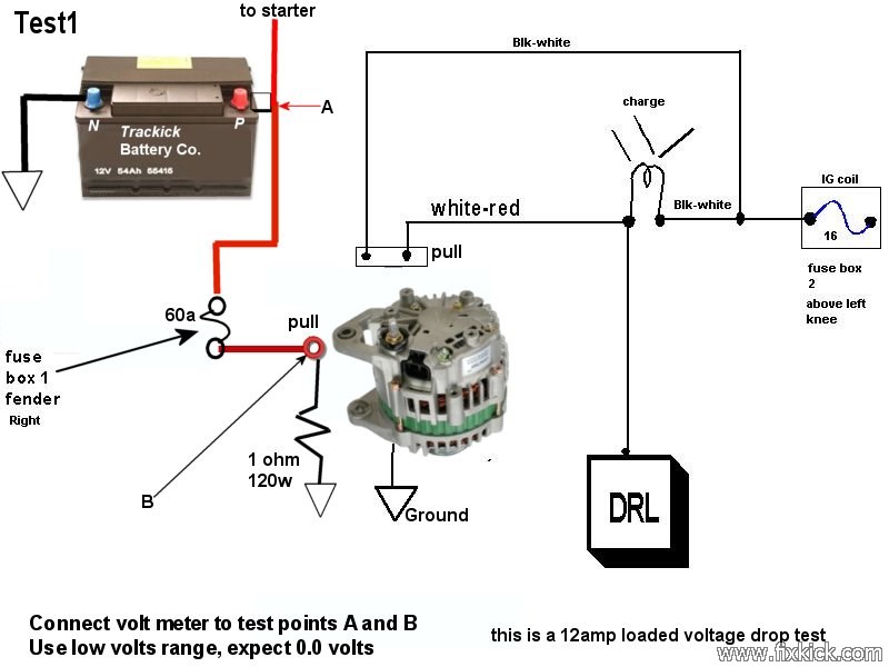
Here are the loaded , voltage drop tests 1 and 2 , expect 0v volts drop during the test. ( charge connections(clean) to attain zero drop)
The Test resistor is sold here.
Warning the resistor will get SUPER HOT (If it don't spark as you connect or get hot, then the test is INVALID)
The 1st test is the most common of all failures, through that nasty wiring in the right fender fuse box, etc. ( I call it the salt belt collection box)
This is the CHARGE FEED DROP TEST ! Do not let the pulled battery charge wire "test1" (RED) at "A/B" touch ground or BOOM !
We are only testing the Large RED wire here, under a 1 ohm load, that is 12amps load, and 120watts, a 150w resistor is best. (hard to find, yes)
They sell a tool that can do this called a battery LOAD testers, at harbor freight, this can be used as this LOAD B point to ground.
In fact, connect point "A" LAST
If the fuse is rusty, the alt will fail. (corroded, rusty or filthy) In fact, any bad point on this main cable feed, will fail if corroded in any way.
That 1 Ohm large resistor, below, can be substituted, with large 10-20aamp , 12vcc LAMP or Huge LAMP bar (off Road lights) over 100watt lamps.
Find something that sucks 10 amps or more, up to 50 amps, and USE IT! Even one of those car electic heaters.... YES !
They sell car 12v hairdryers too. (oddly) They all suck 140watts, and are prefect. the more watts the better.. up to 700watts MAX.
I see a spark as I connect, that is ok, and proves the test is valid. (no spark is a failure) use and ammeter, to see the current flow on the 20amp range)
If you can not get current to flow, the path is open. (about 10amps is normal flow)
If you get current here, and the voltage at A to B is 0 vdc, then this drop test passes. (0.1v spec in FSM) I want as near zero as possible.
If the resistor (load) did not get hot, this test fails. (find the bad connection. and the Alternator, magcially starts working again)
This next tests is the CHARGE GROUND Drop test. Note how I check the whole path ,every inch.!! in one test.
I am testing just the Alternator ground here. sure the battery is fully charged.
The Harbor Fright, battery load tester , again works here for the 1ohm device. In fact , it excels here. The more current you can flow the better the test up to 50 amps.
The normal battery Plus cable is removed with great care and tied back. (safed off this is called)
I connect the resistor from the naked battery Plus terminal to the Load resistor (ADD) then...
Then the other load resistor leg is connected to the ALTernator CASE. (the alternator must be firmly mounted in the engine mounts)
I see a spark as I connect, that is ok, and proves the test is valid. (no spark is a failure) use and ammeter, to see the current flow on the 20amp range)
If you can not get current to flow, the path is open. (about 10amps is normal flow)
If you get current here, and the voltage at A to B is 0vdc, then this drop test passes.
If the resistor (load) did not get hot, this test fails.(find the bad connection. and the Alternator, magcially starts working again)

Regulator facts: (this is all theory what regulator is in any car , is not know (vast clones and even upgrades exist )
The regulators (some) can shut down, with a missing lamp or a burned out lamp.
The regulators can shut down for the following events.
Some regulators can glow the charge lamp for all the below events.
- A break or short in the sense wire (wiring hacks,
most likely lunder the dash)
- The big 6 gage main battery charge drive wire is Open or
resistive (read , corroded).
- Loss of Reg. power pin voltage pin 10 below.
- Over heated alternator (chip senses it) at 170C
- A Field short inside the ALT.
- If the Reg. voltage minus the battery voltage , is greater
that
2.6v (eg: battery 12.6v and Alternator at
10v, it shuts down) Pin 1 below senses this error. LAMP ON.
- Output overvoltage ( but not if big BDX transistor
shorts , if this shorts, the alt is 24/7 full fielded)
- The Alternator fails to self excite (not the below design, the lamp below, is passive)
- Shorted main battery cells. (see rule 6) (too low voltage failure)
- And last, drum roll ..... the alternator is not spinning or the belt is slipping like
no tomorrow.
The regulator must not blow up car electronics (nor load dump it)
The Regulator must not blow up you battery , or try to chrage a battery with only 5 good cells. 5x2v = 10v
It must not attempt to charge any open cell battery or any battery with a shorted cell.
Yes, it has a big job.
The Below is a modern Alernator Regulator chip and wiring. (just to see how things change... and for the better)
More modern regulators run the battery at float volage (charged battery), extending battery life greatly.
Another common reg, is the L9407F by ST
I offer this, for the wildly curious. (not a passive warning light, unlike many old cars) (no more dead alternator, every 750 hours of lamp life, imagine that.....?)
The chip REG, modulates that light, and the lamp is not necessary, in this design.
The Chip keeps the Altnernator off line until the engine is running , allowing better starts in extreme cold weather, or you left the headlights on by accident.
The ALT free spins while starting the car, it don't add DRAG.
On many new cars, the ReG is missing and the ECU controls the ALT at ALL TIMES.
See the full data sheet here.
Last, is my 1996 NOOB charging diagram.
Nobody DIY fixes bad Alternators? ever see the parts prices, ouch, but Suzuki does sell the internal parts and lists them, for big $$$
Actual internal Alternator failure mechanism's and symptoms: A hit list:
- Bearings bad or seizing (a squealing fan belt?, noise from bearing , yelling to you, I'M BAD !)
- Brushes bad ,worn to nubs or gone , (weak or dead alternator or intermittent op.'s).
- Rotor coil open or shorted , (weak or dead alternator or intermittent op.'s). open coil ,kills Alternator dead as a door nail.(a Roman refr)
- Stator coils open or shorted , (weak or dead alternator or intermittent op.'s). and EMI noise (elect. noise, heard on AM radio?) For sure with a SCOPE.
- Bad bridge, opens or shorted ( (weak or dead alternator or intermittent op.'s). and lots of noise if shorted, EMI will happen (Electronic -Magnetic Interference)
- Bad diode trio, opens and shorts, (weak or dead alternator or intermittent op.'s). the regulator goes quite nuts.
- Bad regulator, (this can be bad, in many ways, causing a vast array of complex or odd and intermittent symptoms or just kills Alternator dead. and Dash lamp odd indications.)
- Rusty grounds, on case and all the way back to the battery , can kill a good alternator (only causes a good ALT to misbehave)
- A Bad rear connector or bad dash lamp, to same, or any of it's wires not conducting or grounding out.
Hint, Avoid China made clone Regulators like the Plague. ( or the whole thing for that matter). Buying no name parts, is a mine field of grief.
Parting shot:
I was once stranded far from home, no cranking possible , just CLICKS.
I wipped out my DMM (Heathkit meter, a relic) and found the battery at 10v . BAD.
I removed the CAR battery , rolled it over end for end., on the grass shoulder 2 times. and bingo it's 12v again. (hands now have acid on them ,so dont rub eyes ,etc)
One cell was shorted, now it is not. (the bottoms of batteries fill with lead mud and short cells; this can be upset by rolling it.)
Car started and I went home. You are not helpless. Use your water bottle to get acid off hands, now that car is idling.
You can also hammer the starter casing with a rock to wake up a dead starter. (this is not a permanent fix, it's for stranded folks only)
Last, but not the least ,here is the Alternator coming on line, at 14v. the left side, is the moment of starting the engine, and time advances to the right.
My AMP clamp has logging function and can do this plot too, (it's a fancy FLUKE meter)
A DSO scope view #1 below (digital storage oscilloscope) aka; a lab scope?
The fast drop to 8v is the huge 100amps, the Starter draws (yes, the battery has resistance about 0.08 ohm) then the wavy line is cranking, then the uptick (starts)
Finally, see the Alternator come on line?
Note, it took only 0.6 seconds to start the engine. (engines don't turn on, they crank, then START and self sustain (EFI sustained).)
The time axis below is a full 2 seconds. The falling edge is the Starter energizing. about 100amps.
The drop is the battery resitance, (internal cell resistance) the cables can drop 1v. max.
the last rise, below is the ALT waking up.(Mr. Faraday comes on line)
If the 12v line says at 12v, after starting, the alterator is bad (not spinning fast) or failed to self start.
If the 12v dips below 8v, the battery is weak(or not charged or bad) or the starter is shorting inside.
rev.11 more regulator facts, added the full field test, fingers crossed. (a major update) 3-15-2013 9-17-2013, edits. more bench marks.