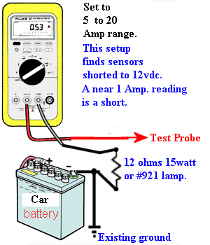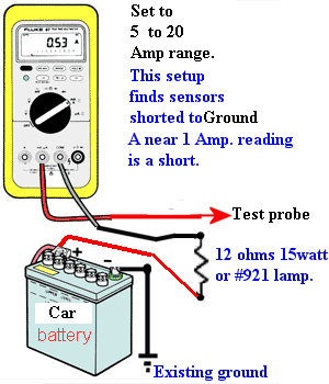
A DMM and 12 ohm 15 watt resistor or any #921 lamp. (tail lamp)
These tests proves the new ECU outputs will not be blown out.
Related pages: DMM and Blows Fuses.
In each case, I do recommend having the real FSM to see what I'm doing here. (or alldata.com account){ or the 1 day $4 pass here}
What I am doing, is making sure, no wires or coils are shorted, as both can blow ECU output pins.
As and added precaution, disconnt the 8v MAP or 16v MAF sensors, for test mode DWG2.
8 VALVE G16 ECU: 1991 to 1995
(The FSM shows ECU ohms on pins but is near useless due to so many open circuits with the key off, and key on blows up the ohmeter, or at the least crazy readings.)
Not only that , it's better to to 12vdc testing, not Ohms that uses, 1/1000 amp currents.
If paranoid, (I'd be) the only way to make sure a car is safe to run a new ECU is to:
Pull ECU from car.
Then with a 12 Ohm , 15watt resistor . (or lamp)
Set the DMM to Amps. (not milliamp's)
Set to 5, 10 or 20 amp range.
Next connect the resistor in series with the meter negative lead.
Connect resistor free end to ground and Red meter lead to the battery Plus term.
The meter will read 1 amps. this pre step proves the meter is working, and resistor is 12 ohms.
End pretest, setup: (we must do this or never know the next tests are valid)
Test 1:
Now keep meter, to same minus meter to resistor path to battery minus.
Turn key on, there is still no ECU installed.
Place a jumper wire (paper clip?) and jumper harness wire pin B15 to ground, the enables the MAIN relay, with key on.
This allows my fancy test below to work. (true currents)
Then, with the red test lead (DWG-1), touch each wire in the ecu connectors, that are outputs. Not a lot really.
The B pins are Green connector. See here for locations:
A8, A11, A12, B5, B6,B8,B13,B14,B16,B17,
This test measures all the coil currents. VSV and relays, via the added, series 12 ohm resistor.
Some will read, from 0.1 amps to .3amps. none will hit 1amp. or that object is shorted .
The B6 Pin will be the highest.
Put the DMM Amp meter in-series with this lamp and if there is a short, it glows but no matter what, the ammeter will show you the degree of short.
The VSV valve coils draw 0.36 amps, max. not ever more. or the ECU is at risk to burn up.
The ISC pin B6 will suck current at 1amp. it's a 12ohm coil. most others are 33 ohms.
Only touch this pin, B6 for only a few seconds max out of 1min cooling time. it will read near 0.5 amps with the resistor or 1amp with the 921 bulb.
That is how I'd do it, I dont trust the FSM ohms test, sure its valid but I want to use real 12v power, to see it work or not. (rubber meets road)
pass or fail.
end test 1:
Test 2: (DWG.2)ECU unplugged, key still on. ( and my main relay jumper still in place.)
INJECTOR TEST. The above tests proved it's not shorted to 12v. The below checks ground outs.
Now we will check just 2 pins for unsafe ground outs, Pin B8 and B17 (injectors) Keep the B15 jumper too, for best effect.
The injector now is floating with no ECU, installed. zero current is the only possible results.
Move the resistor free end, from battery minus to battery plus lug. the resistor is still in-series with the black meter lead. See DWG.2
This creates a high current virtual ohm meter, in effect.
I touch the red free meter lead to B8 then B17. zero current. allowed.
No current seen on the meter display, this is a PASS condition, test passes.
If you get any current , then unplug the injector connector.
If still current now, the wires for the injector are shorted. I'd run fresh wires.
If current stops now, injector pulled, then the injector is shorted inside, to ground, (near impossible but I keep open mind)
This test proves the car wiring is safe for any new ECU.
DWG.-1 DWG.-2


16 Valve ECU G16 engine. 1992-1995 only.
Same test but DWG1 is used on a different set of pins.
Remove , ECU, fully or the connectors to it.
See here for pin locations.
Test 1:
Ground A10 pin, Enables MAIN.
Key on.
Using the same Test #1 above, probe the pins, A4,A5,A14,A15,B12,B22 &B25 (Only pin B12 will have high currents. 0.5amps. most will read below 0.30 Amps.
Next, do test using same setup as above. DWG1 to the 4 injector pins.
TEST 2:
Pins: B11,B13,B24,B26 (injectors)
Do so key on, and the A10 jumper in place.
Expect about 0.5amps. (10 ohms injector plus a 12 ohm resistor is 22 ohms. ) I = 12/22 or I = 0.55 amps ; if readings gets near 1 amp? flow, the wires or the injector is shorted.
Only touch the probe to pins, for 2 seconds, only enough to get a reading. Do not overheat the injector. The injector will see about, 6volts only.
If too much current flows, disconnect THAT Injector. If it still runs too much current?, the harness is shorted. This failure mode, will blow up a good ECU, for sure.
1996:
Uses DWG1 on pins E34 pins, 4,5,10,14.15 and E33 pins 6,7,11,13,24,26) see here for colors. and locations.
In 1997- 98 Suzuki switched the ECU to PCM, by Adding the TCM logic into the ECU and deleting the acutal TCM, this was a major change.
There are 3 connectors, to test E172 , E173 and E174 (173 is TCM section) (sadly, I have no photos)
Remove all ECU connectors from ECU.
Key off.
Ground pin E172 pin 1, (this enables the MAIN relay) I DO NOT have the Connector ID drawings, go to Alldata.com and it is there.
Key on.
Using DWG1 setup test probe the following pins on E172 Pin 7,pin 12, pin 25 (relay coils) 0.3amps? and pin 11,13,24 and 26 (these last 4 are injectors and will read higher current, about 0.5amps)
Using DWG1 probe E174, pins pin 5, 6 & 11, (relays and VSV coils) (0.3amps?)
Swap Meter setups now:
Using DWG2, we check the shift solenoids, for shorts at E 173, pins, 8,15, and 16. ( these SHIFT solenoids are diode clamped, so will show a short if you use the wrong polarity) These, are 12 ohm coils. so will pull full current (0.5 to 1amp)
For these 4 speed tranny 3 solenoids, I'd be sure each reads, the same Amp.'s, then power down and use my OHM meter, to see the actual resistance of each coil to ground, and that each reads the same.
Do not connect DC power to these 3 pins, directly while reversed polarity , or you will blow up the hidden diodes in the solenoids. If you blow them up, this is lost ECU protection, and not good.
Send only Plus Polarity to the solenoid pins, as seen in DWG2.
Once you find a bad reading, key off, and use the DMM resistance OHM meter mode , to find this short, after a 2nd visual inspection of the path . (Disconnect the battery minus lug, before doing OHMs tests)
cheers !
rev 2 ++++ 3-24-2014 ( need to add 1996 to 98 next)