The Electronic Fuel Injection  (EFI) system of the Sidekick  and it's sensors.(Geo Tracker).                                 

This page is retired, see next link on the next line for the new page.
This document covers all sensors from 1989 to 1998  (3 "USA" Generations)   (see my testing the sensor's and actuator's page here)
(For USA market only and some Canada) [some countries can have carb's up to 1999]  Some non USA cars have OBD1 ECU's up to 2001 and 2006.
Keep in mind that Suzuki/Geo made these cars, with over 30 configuration's world wide,  with 5 more more engines. and carbs , EFI and different ECU's and different smog parts. (we have only 2 engines, in the USA, this year span)
In fact ,some JDM Vitara's( designed only for Japaneese Domestic market,) have no SMOG devices (nil) no O2 , no EGR , no CAT sensors or devices, at all, and no closed loop controls)
I will not show any information about any Carburetor based engines.  Carb's are obsolete here, in the USA, and the manuals are long out of print.(parts are rare)
his covers all the input functions of the PCM/ECU  electronic fuel injection system. (and most  output devices)  The ECU bacame a true PCM in 1997 when they added the TCM function onboard the ECU. (PCM)
This page explains the sensors and actuators and  how the  ECU functions in great details.  The above link shows, doing the tests.


Back ground information:
This page helps you find the location of all Sensors ,and other parts, in the engine bay

MY SCHEMATIC PAGE:   ( full data how to make engine run , electrical  data. 89-96)


Here are some offsite good information on sensors and acutators.


To understand this system, you must become familiar with the Component names.  (  about 18 critical sensors)

SENSOR NAMES (red are  critical components , to starting and keep engine running):

Click on the left column sensor names, to jump to my information on same.

SAE j1930 names in black bold fonts.  Standard Terminology list,  This short list is the SAE.ORG list.  a standard.

The best way to view sensors is live with a real scan tool.

If no scanner, you must the tests by hand.

Sensor
name
Alt.
name
Function  Sensor or device.
Items in RED are critical in starting the engine.
Location (typical)  89-95.
IAT
ACT
Air temp, or Intake Air Temperature  sensor. IAT
In the intake tube or the intake manifold plenum, not critical , it fine tunes!
ECT
WTC
 Engine Coolant Temperature senso  ECT
Screws to water jacket on block or water outlet of thermostat housing.
MAP
---
Manifold Absolute Pressure. Critical after Starting. MAP
Connected to intake manifold plenum. Vacuum sensor, electronic.
TPS
---
Throttle (valve) Position Sensor  TPS  with switch
On the end of the Throttle Body butterfly shaft. A Variable resistor.
O2S
EGO
Exhaust oxygen sensor  O2S ( HGEO = heated )
Located in exhaust manifold  (on old cars),  new cars have 2 or more
VSS
---
Vehicle Speed sensor.  VSS
Just a rotation counter on the speedo cable.  Cars speed is measured.
CMP
CAS
 CAM angle sensor.    CMP
Located in the old Distributor or on Cam shaft end , on newer cars.
CKP
CPS
 Crank position sensor   CKP  (96 an newer)
Located on front of oil pan and reluctor wheel behing crank belt cog wheel.
EGR
---
Exhaust Gas Recirculation devices   EGR
Located on Intake manifold and is not a sensor (but is,on somecars )
MIL
CEL
Maintenance Indicated Lamp ,Check Engine Light On dash Lamp shared with  SES. Service engine soon.
PCM
ECM
Power train control module   PCM  EFI controller (suz)
 89-95 is behind left front speaker.  aka:ECU,ECA,ECC, BRAIN or Puter
MAF
AFS
MASS Air Flow, Sensor  MAF
Located  on Air tube between Throttle body and the Air cleaner. 95 and newer vehicles and all 16valve engines. NEVER touch the HOT WIRE!
ISC
IACE
Idle speed Controller (a output actuator device)  ISC
 ECU Idle control valve. Electric modulated Idle control device.
IAC
IACT
Idle Air Control  IAC  usually a thermo device
Located on base of Throttle body "TB"  both MPI and TBI
Misc.
---
Injectors, Ignition coil, Fuel pump, outputs
Starter monitor, Battery voltage monitor. 
MPI
TBI
 Multi Point Injection and Throttle body Injection.
 16v is MPI and 8v engines are TBI . Vastly different EFI designs.
EVAP
---
Evapoative Emissions
 Large black charcoal canister and vacuum control purge valves.
TCC
---
Torque Converter Clutch (solenoid)  TCC
 varies by year, some PCM's (newer) have no relay ,ECU has direct drive.
TCM
---
Transmission Control module,  4speed only
located high in dash above right knee behind ignition key level.
The EGR is not critical but engine may not idle , nor may it have full power if the EGR is stuck open, or inop.
If the EGR closes, and you defeat it , you can test all other features, to make sure all is well before , reactivating it. (pull the vacuum hose and put in a golf tee to stop the sucking of fresh air.)

DLC = Diagnostic Link connector, near battery or near right front headlight shell rear area.
DTC = Diagnostic Trouble code (blinking CEL or scan tool data, after 95')
WOT = Wide open Throttle.
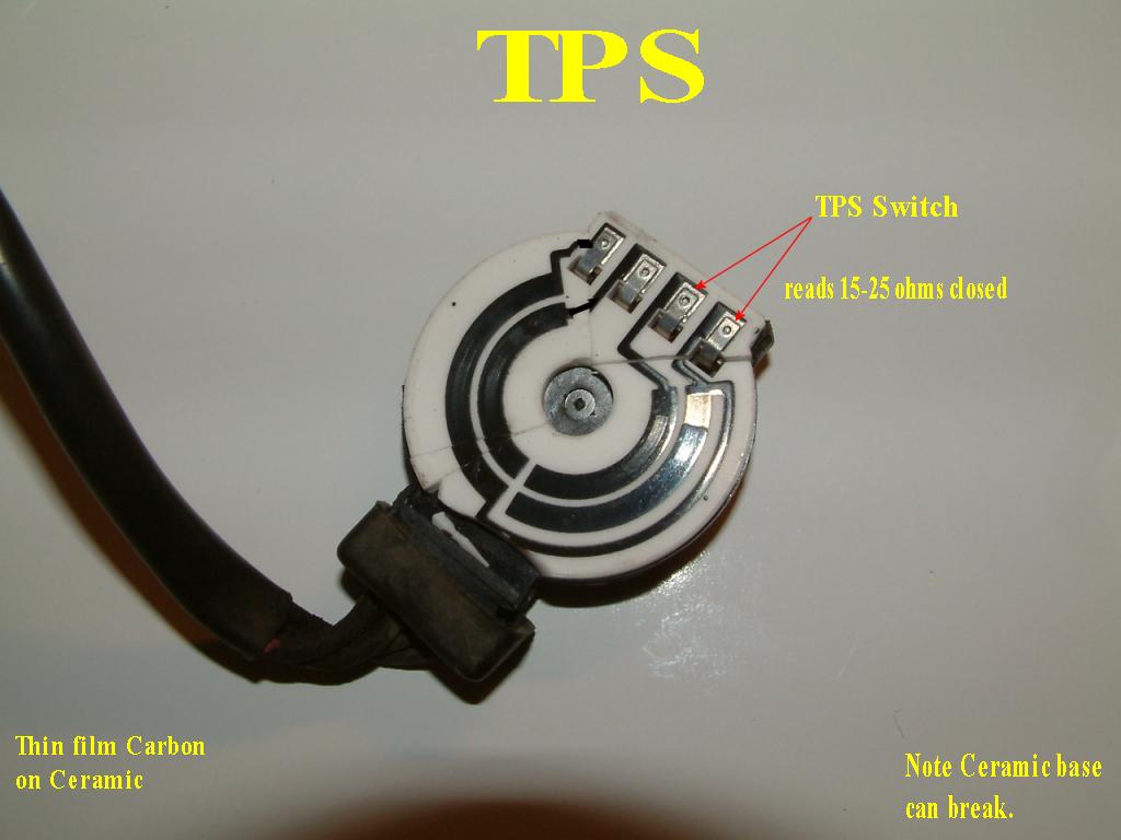
TPS  switch, this switch is inside the TPS and signals PCM to enable full Idle controls , if engine is hot.

Look here to find all the parts above, on both  the 8 valve and 16 valve engines.


16 Valve Engine ECU voltages:


VSS sensor:
Vehicle speed sensor.  ( used for Cruise control, for SES warning,  and Oxygen sensor monitor and last it helps engine cut fuel when coasting down hill or even while deaccelerating in gear.)
Located in the speedometer dash head.
The Transfer case has the speedo gear that connects to the speedometer via a cable, this cable spins only in gear and moving, so one must raise one rear wheel and drive slowly with full wheel chocks to test it.
This speedo VSS switch clicks abou 4 times per revolution of the speedo cable.  (the ratio of clicks to speed is stamped on the bottom edge of the speedo face plate (cover off).
Connect an ohm meter (DMM/DVM) to the VSS and measure this closing and the opening of this this reed switch.
If this sensor is dead (broken speedo cable anyone?)  the ECU will be running in limphome,  the cruise control will be dead, the TCM 4sp will be very upset and malfuntion and the following modes, will be inop
in the ECU/PCM  :  O2 (O2S) monitor dead, Fuel cut, EGR dead, EVAP dead., SES mileage timer dead (a blessing really).

Repair  the VSS
when the ECU sets the VSS DTC codes.

With this sensor dead the ECU runs like a pig, wastes fuel like crazy and has very poor power, and will over heat the Cat converter and insure its early demise.

PCM:  (ECU)  ECU is the 89-96 name the in 97 it's PCM  (engine control then power train control, module.)
CHAPTER 1: 

A Review of this old design  Early 90's , ECM: (8 valves discussed here)
The ECU, controls all the spark and fuel injection , plus it maintains a near perfect air fuel ratio, using a range of special sensors.
TheECU is the fuel injection controller and spark generating and controlling device.  (job 1)
The ECU, is multi-modal, it has many modes of operation ( start, run , engine cold, engine hot, and failsafe and Limphome. ).
The old cars can detect gross errors in the system and then throw error codes , glowing the dash CEL lamp and throwing DTC error codes.
"my Check Engine Lamp is on"  From now on I will call this a CEL.  The errors are called DTC's, for Diagnostic Trouble Codes.
Do not unplug the battery cable to clear this code, but rather, please PULL the code or codes , first. The Dome fuse resets these codes.
See how to read CEL below:

Theory of Operation: ECU:

There are 3 (of 5)  main modes, "Start , Run Cold and Run HOT , The Hot mode, has two sub modes called  "Open loop and closed loop" 
 (fyi: open loop uses canned fuel mixtures indexed by air flow, but closed loop uses the Oxygen sensor (and the MAF + IAT [16v]  to make a near perfect Air and Fuel mixture)

The start mode (has 2 sub modes, cold and hot start)   Keep in mind Start mode is the most simple to diagnose !!
The START MODE needs very few sensors to function.
There are 2 more modes, Limphome (failsafe) and backup, which are only used when some sensors are dead.

HOT or COLD COOANT , determines the start up mode.
If the engine is cold  and the ECT says the engine is hot , the car will start too lean and will run very badly (lean) or just begin idling too slow and die out.
If the the Engine is hot and the lies ECT and reports, the engine as cold , then the startup and run will be very rich and mostly flood.

The ECU has the job of creating spark 91'+ , and spark timing, and metering fuel (all years) to the engine.  (cept on 89 carb 1.3L engine)
 The ECU is just a small microprocessor, running software factory software (firmware) It is near impossible to change this code. (it has no Flash®  memory)
All Fuel mixtures, and timing are stored in tables, the sensors tell the ECU what parameters to use in these tables, or uses math equations to calculate injection rates and spark advance.


To start cold the engine , the ECM must be powered up and the MAIN relay working.
Pins B1 and B7 must be hot ( 12 dc)  The  MAIN  relay must be pulled in or many functions are DEAD ( like spark !)
If  you attempt to start the engine , the clutch switch must be good and engaged (held down).  (auto tranny's must be in PARK and its start switch closed)

Once cranking begins:   
The ECU must have a working ECT ( this coolant sensor must reflect the true Water Temperature or all bets are off. )
If this value is good , then the following sensors are needed to start:

The Major Players:  ( A Nut shell list)


On modern engines all sensors ,work together to get the exact flow rates of air in to the engine with the help of the IAT (Intake AIR Temp. which corrects for air density via temperature readings).
All Sidekick ECU's try to start and run even when one of the 3 or 4 airflow sensors are malfunctioning.  Suzuki calls this act , FAILSAFE, and most sensos can be mimicked by the ECU, but never the CMP.

How ever my  8v Side kick will start with only the CMP, and TPS connected. ( This information can be used as a troubleshooting aid)
 (Note:, with my 8V MAP , IAT, ECT  unplugged my Tracker  starts ! and runs , but poorly, and rich and low power ).  This is called MIMIC mode in the FSM.
With the MAP unplugged, the motor wants to stall and the fuel used is HUGE. Do not run with the MAP unpluged and only for a very short time or the CAT will try to melt.


#1- The CMP/CKP)  (Cam  Position Sensor , there my also be a  Crank Angle sensor)
Crank angle sensor  CKP   ( angle and position mean the same thing)
Cam angle sensor,   CMP   , some car companies call both a CAS. (or crank CAS, or Cam CAS)
Crank/CAM  angle sensor. CAS , I mention because this term is common today, but old Suzuki does not mention it.
COP or C.O.P  = coil on plug as in all 1.8L Suzuki SPORT cars / Esteem's , and larger engines.  Distributor-Less Ignitions.  ( not the Police cars)  The 1.8L has no distributor at all.

First off , TDC means Top Dead Center.  (the piston is at the top of its stroke and is firing)

Some people call the  Distributor  a Dizzy  (which is very slang) .
A distributor has a black plastic cap and has 4 or 5 high tension spark wires , routed to each spark plug.

These sensors are really generators of pulses , the timing of these pulses , coincide with Crank TDC and or #1 cylinder TDC.

Without  "cam or crank pulses", there will never be fuel injection , nor spark !!!   (always, check for spark, first on NO STARTS )
Most COP cars and 96+ cars, have 1 cam and 1 crank sensor, others have a dual cam sensor yr. 2000+ , which eliminates, the crank sensor.(oddly).
In 1996-98 Suzuki 1.6L integated the Distributor with CMP, coil, ignitor and only has 4 wire on the Distributor cap.  It has direct Cam sensor too.
Keep in mind the ECU needs to know Crank TDC point and when #1 is firing.   On a distributor-less ignition the CAM sensors (left rear cam of 2) replaces the Distributor.
The 8v only needs 1 sensor and is located in the Distributor base. 
The SAE name for the NO Distributor  cars, is  "DI" or DIS  Ignition systems started in 1999 (1.6L) and in 1996 1.8L Sport models.
This is because the 8v fires at every TDC and the ECU does not have to decide which cylinder is actually firing.  (the Distributor cap/rotor ,decides that, thus the name distributor ).
Newer 16v engines have both one Cam sensor and one crank sensor. (usually for better firing accuracy and OBD2 regulations for misfire testsing. "Monitors")
The basic difference between a CMP and CKP(96+) is the number of pulses generated, per revolution.  The CKP not subject to the belt jog or jitter of the CMP, making MISFIRE detection easy.
The cam sensor is crude and signals  a true  TDC firing, and is subject to lots of belt or chain (1.8L) play and resulting sloppy timing. (and wasted fuel and extra smog)
The Crank sensor is far more accurate and does not have, slop or wiggle to it, it may have many teeth in order to exactly time each cylinders TDC point.  (OBD2 requires a CKP)

The ECU (with ignitor and coil) Generates all spark ,the CMP/CKP tells the ECU "WHEN". 
The ECU creates all advanced timing from calculations and tables.(maps) ( except in 1989/90 the distributor is self contained and standalone for all spark and all advancement)


The loss of CMP, kills all spark.(on some cars the loss of one can mimic the other in" limp home mode", I not sure if Suzuki can do this)

A great TIP: (89-95)
With the DLC diagnostic jumper in place , you may  get a code 41 or cod 42 , for crank or cam  sensor failure , DURING  5 second +CRANKING ! (keep key on after start fail to see this code)
If the tachometer is dead cranking, there is no spark (code 41 or P0340/355)  or the ECU no longer has over 10v power.(lost power to ECU)

Warning:
Do not run the ignition coil with no HV spark loads, that is running the HV side , open circuited.  This an cause breakdown of the parts, and flash over is real bad here.  damage to CMP, ignitor or ECU (or you) is possible.
I don't short the spark plugs dead to ground. This can overload  the Ignitor. Use a dummy spark plug (or a real one gapped to 0.028")

The basic CKP sensor (pulse generator), tells the ECU when the crank shaft passes Top Dead Center, each and every time.  It is an electromechanical device.
 ( a magnetic coil  HALL device and an shaping amplifier , on a Sidekick it generates a  perfect 0-5vdc, square wave, that computers love to see.)
Earlier cars (89/90) had Variable reluctance CMP or CKP devices and are very subject to noise, position errors, these are getting rare to see in shops today. These 2 years, the ECU has no role in making spark.

Where are my sensors?:
The 8v single sensor is in the  Distributor base only.
16v , in Distributor base and below the crank shaft, all the way forward of Oil Pan.
1.8L has 2 Crank/Cam sensor devices , both are called  CKP, one  on the cam shaft end (this is no Distributor on 1.8L, it  is Distributor Less Ignition with 4 Coils)
and the 1.8L Crank (CKP) is near the flywheel, at a rubber grommet.  { note here that the 1.8L engine is just an ESTEEM engine 1.8L, this can help you find parts easier !)

On cars with no Distributor (DIS 1.8L) , you need two sensors, cam and crank , one signals every TDC, the other signals #1 TDC. Together they allow the DIS ignition.
The Suzuki Sport 1.8L has the first  DIS ignition.  96/98 , used in Sidekicks. (and 1.8L ESTEEMS)
DIS = Distributor LESS , Ignition System.

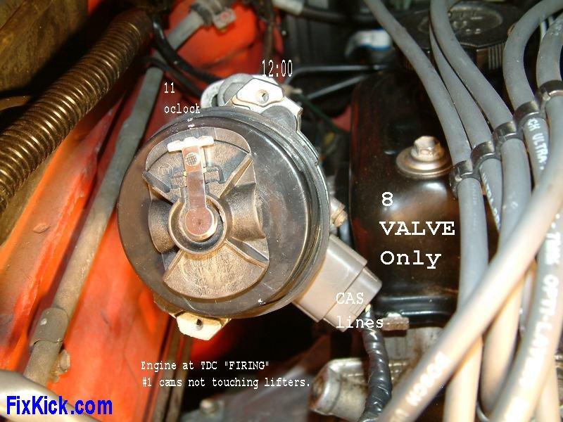
Here is my  Distributor: in  8 Valve 1.6L engine:

  My Distributor, click to zoom.

See that wire, in black at 4pm, that is 12v Power , Ground and Signal out.
The CMP is located in the Distributor under that plastic cover. ( never run any Distributor with out the under rotor cover ,as the HV will flash over and destroy the CMP sensor !!!)
HV= High Voltage.
The CMP tells the ECU when to send spark commands to the coil.  Just  like a drummer boy to a band.
No CMP  signal,  results in No Spark and for sure NO INJECTION !!!
The ECU stops injection for safety, if it "thinks" spark can not be generated!  (crash safety and engine flooding safety)
The ECU monitors the Ignition coil primary for spark feedback, to perform this  monitor.

As you can see this CMP device replaced the old fashioned ignition points  ( a blessing).
Testing the CMP with out a SCOPE is a tad difficult, but one can remove the Distributor and spin it with a  LED , a 500 to 600 ohm resistor can and a 12vdc power source.

The LED will flash 4 times per 2  revolutions of crank or 1 revolution of CAM/Distributor.
The CMP can be tested on or off car. and with and with out the cable attached.!
Back probing the CMP connector with scope or DVM works easy and simple.

The FSM method is with cable attached and   voltmeter backprobed from ground to Signal pin.   FSM = Factory Service Manual.
FSM: , crank and see +5 , 0v ,the +5, repeat.  2 cycles, per turn of crank.

The 91 to 95 CMP with Distributor can be tested on a bench with a 12vdc power suppy and any meter, scope or test LED.

If we have this 5v square wave ,then we must have spark now.

The 1989/90 Variable Reluctance sensors, in the Distributor, can be problematic. See 60A distributors here.
There is no timing freeze jumper for this stand alone Distributor.
These early Sidekicks 88-90 had VR CMP sensors with only 2 wires. < this is a Sammuri
The gap on the VR must be set , see that here.

They can be much more difficult to test and get working correctly. (unlike a 91'+ Hall Sensor)
If your CMP/CKP  is good and you still have no spark, you need to check the CEL codes while cranking and the IGNITOR and COIL next.

The pre 96 cars throw DTC 42 if the CMP is bad, starting in 1996 it throws P0340 DTC. OR 355.


#2- The next critical sensor,  is the TPS:  { the throttle position sensor }

The TPS
must be working , to start the engine , once started the MAP/MAF will fine tune the mixture.
The idle switch portion only single engine is at idle.
The TPS   (throttle position sensor) is a variable resistor called a Potentiometer, to a technician.
 It is just like a volume control, on your old analog radio.

What does this TPS sensor do?
It does many things: (unflood, Acceleration enrich mode, Cut fuel (deceleration) WOT mode,  and detects a steady gas foot)
Key-on , no start, and full throttle , the ECU detects this and shuts down the Injectors, for what is called the Un-Flood mode.
Running, with  a  full throttle?, this causes ECU to go to into W.O.T (wide open throttle).
 ( A special mode of the ECU that gives full and extra power for passing ,etc. WOT)
It also tells the ECU, when you make a sudden change in throttle ,  for  Acceleration.  ( momentary enrichements 
Deceleration mode. ,  causes the ECU to shut down the injectors (saving fuel )  Called cut fuel mode during Deceleration in gear using engine braking.
Acceleration  mode  causes the ECU to enriches the mixture for just a moment to prevent lag.  ( just like an old Carb, using it's accelerator pump)
IF the MAP dies or the MAF, the TPS will be used for air flow calculations via Limphome dead sensor mimic features.

All stock Fuel injected cars have at least a TPS , in addition, they will have a MAPor a MAF sensor.
The MAP  is an Electronic Barometer ( an air pressure transducer).
 
"Fail Safe" mode issues:  ( aka: Limp Home Mode)


G16A/B engined cars have a TPS switch (inside the TPS) that can go bad, and when it does, idle controls end.
The Suzuki Sport 1.8L has no such switch, it detects TP voltage at 0.5 or less for idle.
This switch must be below 500 ohms (300 is good practice) when closed at idle, or the ECU idle controls fail.

The MAP sensor is the primary device for calculating the amount of air flowing through the 8V engine . ( HOT and COLD).
The ECU can use the MAP and IAT ,and ECT live data to find the exact amout of air entering the engine ( using ECU tables).
The MAF sensor just measure air flow directly and accuratly.


Fail Safe mode will usually, result in a huge MPG drop. The car sucks gas like crazy.  
Some people report  15 MPG !
On newer cars this effect, is far less., but is a serious factor.
  ( mine runs very rough and rich and retarded, with all sensors  disconnected, except the TPS) You can not unplug all sensors or the engine will die. Even in mimic mode limhome.


INJECTOR (s):

On the 8V TBI injection system, you can watch injection live !,  wear eye protection and a wool ski mask while looking (back fire is nasty risk).
USE A MIRROR TO LOOK, OK? with a helper to crank, if you have, a no start issue. Look for spark then injection on any TBI car (SUZ calls it TFI)
Never wear plastic ( or loose) clothing when working around any car or any source of fire , ever !   (cotton, wool , use natural fibers, is the rule)
Crank and look for injection squirting, on a no start engine.

MPI Fuel rail injectors can also be tested  by doing the balance testing here.

The FSM  shows you how to test every single sensor.  ( the "EFI supplement manual" from Suzuki is quite fantastic , non better anywhere!).

Want to learn more, about EMS ( Engine Managment Systems ) Look here:

More info. on Injection and pumps here.


My car is THROWING  DTC Codes :
(what ?)    ( Diagnostic Trouble Codes)
 ( the CEL lamp is inside the Instrument cluster,Marked as "Check Engine Lamp")

It is very simple , the CEL says ,something is wrong, and the DTC, says what is wrong.

How to read the DTC

(1986 to Present')
Reading the error codes, is easy and can cost nothing to do it.  ( if you have OBD2, 1997+ , then it costs $30-50 at the HF ,mentioned above)
If you do not get a code 12 , then the ECU is most likely dead.  12  = normal.  ( you must get a number , nothing means the ECU is partially dead and or grossly malfunctioning )  < very common on eary Kicks. 1990- 1994.

Your car tests the CEL lamp, at key on, after starting the engine, this lamp must go out ( normal), but if not, you have trouble.
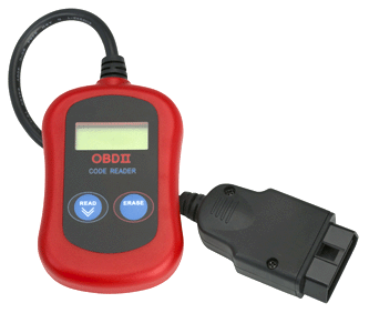
A typical OBD2 code reader for 96 and newer kicks: 
Most scanners and readers, can clear the DTC failure codes, pulling the battery connections, does not clear codes on all OBD2 cars. (by design).
scannerA code Reader for 96 and newer cars.  Other older cars have other methods and devices for pulling codes.


Some times, a DTC will tell you exactly what is wrong with your car.  Like the Heater in the #1 Oxygen sensors is bad.  (believe it).
Other errors, must be used, as help to hone in on a problem.
It is always very helpful to have this information.
Do not start buying  all new ignition parts , just because you get a MISFIRE , DTC.  " It can be many other things , that are wrong".

Better is to use a full scan tool seen here.

Chapter 2:   Examining the sensors and testing them:

Clue 1:  Always trouble shoot NO SPARK (no start) first because the ECU is programmed  (most) to kill the fuel injection if there is no spark)


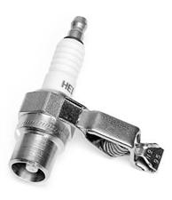
THE DUMMY SPARK PLUG: (get one)
spark    This is the best kind (IMHO) but, there are many more good types.
To test for spark , you should have a dummy spark plug connected (see above photo).
Never short out any spark plug top terminal to ground directly or leave it open circuited.
You MAY damage the ignitor device.[ a huge transistor ]  or in newer cars the ECU will be blown out. ( integrated Ignitor).  < best reason to not do it!
( the ignitor, is part of a  High Energy Ignition, that which generates up to 50,000 volts, to spark the plugs )
The above is Sold in all Automobile parts stores.  It is dirt cheap.  Some guys just weld a clip to a new spark plug.
RESPECT:   ( this is high voltage and can be dangerous , unlike a lawn mower engine with 5 times less power)
50,000 volts, don't touch it while cranking or running the engine.
 It will be very painful! Even dangerous if it passes through your heart !  


If the CAS is bad , there will be no spark , looking for injection, would be a waste of your time, in this case.  

Clue 2:
Please do not throw parts, at your car.  Murphy's law, will make you broke, in short order. 
You need to troubleshoot the Engine managment control system. EMS.
However, throwing a full tune up, on the car is really smart ( plugs ,wires,cap and rotor !)
Tune up's, do not last 100k miles, sorry.

Non start data: (loss of fuel) < look here for more nfo!

Your Tracker/ sidekick will not start, but runs, with a teaspoon of gas dribbled down the Throttle Body (TB) or a 1 second blast (please, no more) of Instant start.
This test proves  that you have spark. ( and that the ignition and valve timing are not off in a major way and that you have compression on all 4 cylinders, if not the engine will SHAKE like mad)   I like to use Propane gas for testing NO START, in the woods, I use "Instant Start" .
If you have spark and car starts with  manually applied fuel, then check the fuel pump pressure.
Clue 3:
Never apply 12vdc directly to the fuel injector or you WILL burn its coil up.  ( some cars allow this, but not this car !)
TBI injector resistance is  1 ohm,  MPI injectors, are 12 ohms.  Both burn to a crisp with full battery voltage applied !
There none too cheap.


How to conduct the FUEL PUMP Tests: 

How to conduct the Injector Tests.


On/off  car sensor tests:
The throttle position sensor, or TPS:

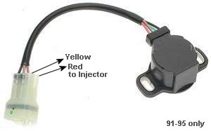
TPS  , located on the end of the  throttle valve  TB, butterfly shaft ! This one is for the 8Valve engine.
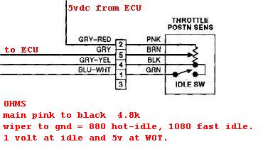
There are 2 sections , or two components in this device a Switch to tell ECU you are idling, and  a Variable Resistor.
The variable resistor or POT. for Potentiometer is not calibrated  by you, only the switch.
The switch must be close at idle or the ECU will never again be able to control idle, the car WILL die at stop signs.

8V config.


Pin 5 above,  will very with from near 0 volts up to near  5v , low speed to wide open throttle.  directly proportional !  No Jumpiness or drop outs allowed!  (voltage or with Ohm meter tests)

The 8v pot. must read  0-2000 ohms at idle position and 2000 to 6500 ohms as you approach wide open throttle
( if pin 4 breaks this  will signify to the ECU that you are WideOpen Throttle , this cuts all fuel injections for ever . This is called Unflood mode. )
If Pin# 5 reads above 3.75vdc  ,when trying to start the car, the car will NEVER start.  The rule for WOT is 75% of 5V.

The TPS- switch portion ,should be closed  (0-300 ohms) at idle and open circuit, otherwise.  ( this TPS has 2 functions !)     ( mine reads 25-50 ohms, and my spare)
Be sure to  force the TB Dashpot plunger to the retraced position before attempting to adjust the TPS switch.  (16v does not have a Dash Pot , cold start fast idle device)
This switch tells the ECU you want it to control Idle and to cut fuel during deceleration. This switch must be less then 300 ohms when closed. My TPS switch reads 15-25 ohms.
Only a DMM meter is needed to test this device. (on or off car) and you can test it on car, using a volt meter and the FSM charts , or disconnect use an ohm meter.
The below links are TPS calibration procedures for the 8 valve engine then last the 16v.

8v Page1

8v Page2

8v Page3


Here is the TPS calibration procedure for the 16valve  92-95 Sidekick or Trackers.

There is no difference in the adjustment on either 8v or 16v engines, only the Pin numbers are  different and there location.

In a nut shell you connect the meter as shown, then rotate (loosen first) the TPS and rotate it just until the TSP switch closes then lock it down.

A.020" to .026" feeler guages placed as shown , makes the job easier.  ( a match book cover works too , if you dont have a feeler guage.)

Sensor has many functions and Roles not to mention, Idle request, Fast Enrich,  deceleration request,  Unflood and W.O.T.  ( 5 things !)

In the chapters above the TPS functions are all explained.

The Below internals of my TPS, are cracked, car will never idle. 
DO NOT DISECT THIS DEVICE AS I HAVE DONE HERE !
Click to zoom , a broken TPS insides.

Remember on 8 valve engines, you must defeat the Dash pot to set the TPS switch. 
Use a vacuum tool or just force it back.  No Dash Pot on 16v ! So, setting TPS is easier on 16v.


8V MAP :
  Manifold Absolute Pressure Sensor:

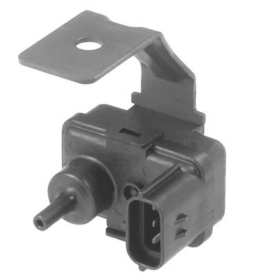
   MAP sensor sits on my firewall and a vacuum nipple connects to the  intake plenum. (8 Valve engine.)

Click Here to see my full Map sensor data , both with a volt meter and with my ODB scan tool.

Keep in mind that this device measures air pressure relative to a perfect vacuum , called "absolute pressure". 
So at sea level it reads about 1 bar. (29.5 inches of HG) with the  "engine off"  After starting it will drop to 20 inches, or about  .67 bar.
Due to this fact, this device shows a huge vacuum, as pressure close to zero and rises positive as you step on the gas .

The map sensor is inversely proportional  to absolute pressure which gives close to 4 volts and decreasing  to towards 0 at high pressures.
To perform a test on this device you must have  home barometer or call a local weather station and get the local Barometric reading.
 ( warning some weather stations offset these readings!  the say adjusted, so do not use that number.)
You then use this equation ,  MityVac reading  minus Local Baro reading = MAP reading.   ( a clone of a MityVac can be had at Harbor Freigh for $25)

EG: Today my local baro reading  is 29.98 Inches,  so I pump my MityVac to 10, so 29.98 minus 10 is 19.98 or rounding to 20, then looking at the chart we should read about 2.5 to 3 vdc, and my bench MAP reading shows 2.8v , which is a good reading.   This 10 in/HG, is simulating 10,000 feet altitude.

I used a "MityVac" (tm) to create my vacuum at the vacuum nipple of the MAP.     I checked the output at , 0 , 5 ,10, and 15 Inches /Mercury-Hg. 
I can test it on a car with the Ignition turned on , not started.  The voltage is then monitored by me with a voltmeter. ( a technique, called back probing, must be done, I use a sewing needle).  I can then test the reading at idle and at 3000 RPM.  and Gunning the engine get really high readings.
You must have a source of Vacuum and a voltmeter to test this device.

This device is not all that accurate, but the IAT , and OXY sensors make up for this inaccuracy.  ( can be 1/2 a volt off and be good)
 ( the IAT will help calculate air density accurately  and the OXYsensor,  helps set perfect A/F mixtures)
On 16 Valve engines the MAF will take over as primary air flow measurements.
This device is easy to test but you must do some math to get the correct values.
The FSM covers these facts , in great detail.

What does it really do ? THE MAP.
This device is the primary Air Fuel governing device on all 8 Valve engines.

From 94/95 engines run with no MAP, only a MAF sensor. 
Most Sidekicks after 1996 have the MAP added back, but in this case the MAP is only used for monitoring the operation of the EGR Circuit. ( It is called the EGR-MAP).

On many modern engines with both sensors , the MAP will be used at Low RPM's and the MAF for middle and high RPM's. ( 99 or newer?)
On some engines, if the ECU detects a bad MAP or MAF  the ECU will drop out the bad device and mimic the bad device using alternate devices.
The ECU in many cars, can Mimic a bad MAP or MAF using a TPS.  "Failsafe mode" does exactly that.  ( 96 or newer OBD cars can do this well).

On all Sidekicks, I believe that the car can , in fact, drive home with only the TPS working, In fail safe mode. ( I did it on my 91', 8 Valve  and othere with 16v MAF can do this too).


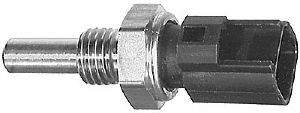
The Engine Coolant Temperature Sensor:     ( ECT is the modern SAE name)
    The ECT Sensor.
alias names: (WTS = water temperature, or coolant temp. sensor)


 The Coolant/water temperature must read about xxxx, at room temp.    low resistance at high temperatures.
xxxx = see chart below , at hot link. or at my test page (last link) for a new sensor I just bought.
This device is only a simple varistor.   ( a resistor that varies, its values with a change in temperature)
The FSM manual states, open circuit is 4-5vdc.
Low temperature shows signal voltage high. (FSM)

Disconnected, this sensor should read 2200  to 2700  ohms at 68 Deg. F (room temp) and reducing to near zero at a hot coolant of 180 deg F.
This is called a NTC, or Negative temperature coefficient Thermistor by technicians.  Rising temperature causes a falling reading.
2400 ohms is typical for normal room temp. water state.
If the sensor opens or goes to a High resistance , in error , your car will race and waste gas like crazy. (the ECU will think that the engine is cold all the time)
If that happens a CEL DTC should set, and your A/F mix will be Rich.
This Device can be tested in a pan of hot water, using a  simple ohm meter.
It can be tested on the  engine with a voltmeter connected  or an ohm meter when its connector is disconnected. [ I recommend the latter test ]

My  data, collected in my LAB. for both ECT and IAT senors.


IAT (old ATS/ACT)  Intake Air Temperature Sensor: 

It looks just like the ECT above and is screwed into the Intake manifold next to the ECT above, on 8V engine.
It is part of the MAF on newer cars and the 16Valve Sidekick. or is screwed into the Air cleaner box. ( some 16v it is completely missing on92'?)
It  intrudes, into the Intake plenum and not the water jacket. ( on some cars the PN is identical to the ECT )
It is just a faster acting ECT, nothing more.
You can test it using the below graph:
The IAT fine tunes the air density readings of the MAF sensor, on an 8v with the MAP sensor this sensors IAT is very important to AFR.
Graph:

Test this device,  just like the ECT sensor. (in a pan of water).
If your IAT is located inside the MAF , it must be tested on car (unless you have a source of hot air to blow in to the MAF)
 [ wifes hair drier?, boy your in trouble now! ]


THE TB INJECTOR:   Used on most 8 valve engines.  [ LOW IMPEDANCE INJECTOR WARNING ]
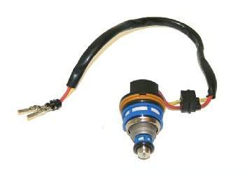
The fuel injector , inside the Throttle Body (TB)

The fuel injector coil must read 0.8 to 1.8 ohms. or the coil is open or burned up. 
Do NOT connect this device directly to 12VDC , OK? You will burn up the coil inside.  It must be pulsed, with a current limiter.!  [ a warning !]
The above tests are simplistic and the OEM manual shows how to test all the sensors and devices, on an off the car and the readings measured at the ECU ports.
This electronic fuel injection system controls fuel delivery by varying the fuel injector pulse width. ( the duration of the injection pulse).
To test this device, first check for the proper pulses , at the two pins above, with a scope or a NOID lamp (a special tool, all mech.'s have in tool box)
You can buy a lamp from RadioShake that is 12vdc and draws 25ma (only) current. 
This will work too. RS,p/n 272-1141  ( you can make one , using an LED and a resistor)
Placing 12vdc directly across this device with a car battery will cause 180 watts to be dissipated on the coil, it WILL BURN UP.
 That is like 2 desk lamps burning inside it. wow! Smok'n!
If you have a pulse generator, then by all means , pulse away.   ( I recommend 1 pulse per second and 2.5 milisecond in duration each )
Well equiped tech.'s have a special tool, for testing this device.  You can buy this tool for about $115 on the open market.  Just Google it.
If bored you can build a 555 timer chip pulser for $1.00 in parts.   I kid you not.  Fire up the iron, dude !
It's funny how every tool , you make, saves $100 .  I love it.  ( It is google-able too)


The IAC PWM Idle valve , mounted to the right side of the TB:    { Pulse Width Modulated }

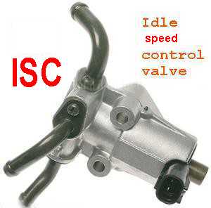
IAC-E:  (ISC) or Idle speed controller.
Idle Air Control Valve , Electric , Actuator.  (hot engine only)

(It has a tiny solinoid that allows the ECU to modulate the idle, at all times under many kinds of load on the engine)
It also OPENS during cranking  ( if not, you may flood) and operates while  running  to proved extra air.

AKA: ISC in some manuals.  Click here to see my testing page on this device..

The ECU can  use this device (above) to accurately set the idle speed.
The above valve works, in all modes of engine operation. (including , start, crank, idle and deceleration )
This  valve could get dirty and need cleaning.  ( the plunger inside is noted for jamming up solid) Click here to see the guts.
The tiny valve inside is PWM (pulse width modulated) by the ECU. The ECU can raise or lower the Idle at will. 
When you turn on the A/C or Head lamps this device ,  corrects the idle speed, via the ECU signals.
Cleaning can be very hard to do,  I can only say to try carb cleaner and try to wiggle the plunger.
Just do your best at cleaning.  Simular to cleaning an EGR valve.  Remove and scrape and flush with carb cleaner.
Scrap any carbon off the induction Port side. I flush mine with silicon lube spray, after the plunger free's up.
Even removing it and letting it soak over night, in solvent, is a good idea. 
The part that siezes is the plunger shown here.

THE IDLE Calibration procedure is here:


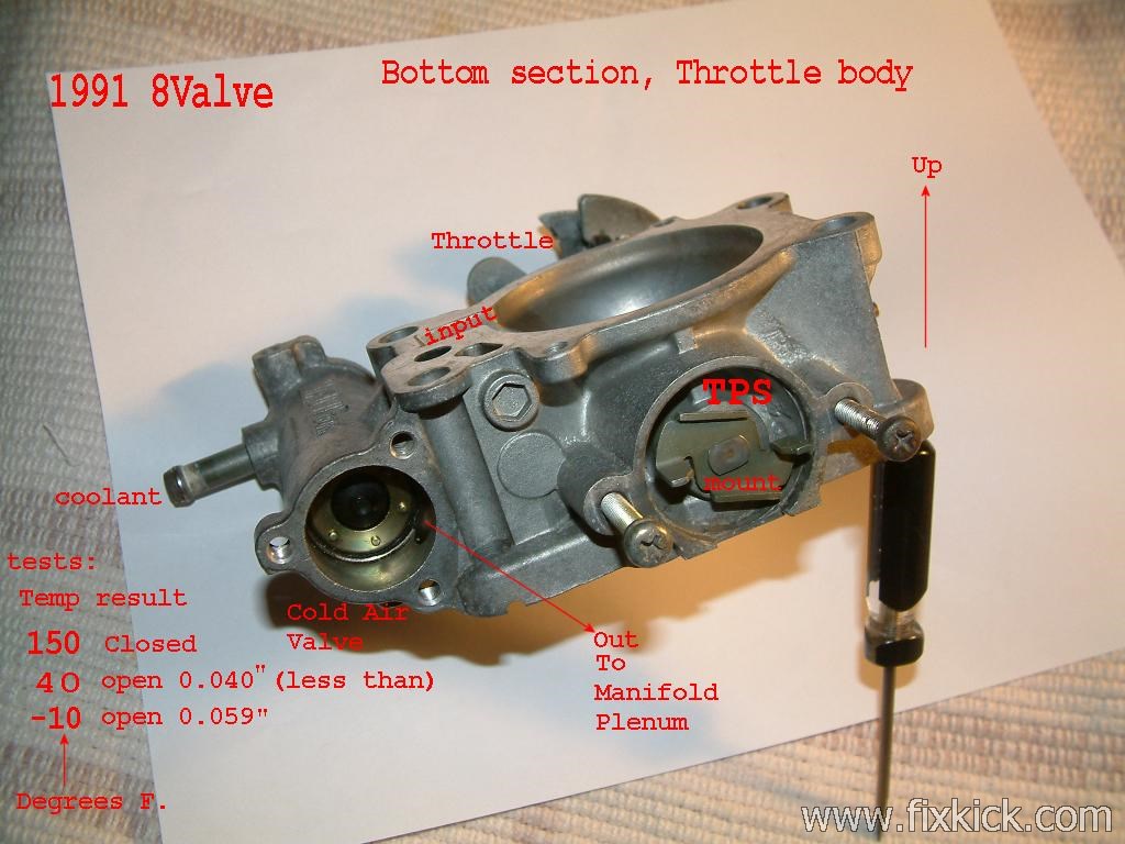
IAC -T:  ( actually this is cold start idle air (extra air for  cold starting)
IDLE AIR Control Valve , Thermal.

This is the IAC thermo, off a 8v engine.  (  I call it  the IAC-T , see more nfo)
The bottom IAC for cold stating and warm up , extra air, seen below.
Just remove the 3 screws below LEFT on the cap and clean it , in place.
Get a gasket kit from Suzuki first, as it will break the gasket , on removal. or make one with NAPA autos.  blank gasket materials. (keep this in your shop for next time...)
See bad idle pages here.

Three tests,  Oven, Refridgerator and then the freezer ( wife is not talking to me....)


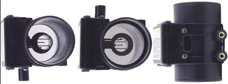
THE MAF:   (The Mass Air Flow Sensor) (Located between the TB and the Air cleaner)

Cars that have this device have both the MAF and IAT sensors integrated (together).

My test proceedures are here:


This is a very accurate device for measuring air flow:  This device comes into play, when the Engine is HOT.
Used on the 1992 or newer Kicks, with the 16valve heads.  ( Older 8v Kicks, don't have this sensor, so they use the MAP sensor)

BTW: the 16 valve engine can be identified by a Side Draft Throttle body and the words 16 Valve on the Valve cover.
Cars with a MAF are 16 V and all newer cars starting mid year 1996


If your car has a MAF sensor on the main air intake tube (16-valve or 96 and newer) then it can cause the engine to run badly.  Loss of power while HOT.
It will eventually coke up.  This is normal and must be dealt with by cleaning it ever 30k miles, or so.  Ignore cleaning the MAF at your peril.
If you have an after-market "Oil Soaked cotton Air cleaner" Krank & Nutz filter , it can quickly foul this sensor.  Dump it , and get a stock filter.
I just spray "CRC MAF sensor cleaner"   into this unit.  Just remove the clamps to get access.
Not all MAF's can be cleaned , some are so sealed up , you can get the spray anywhere near the elements.

Not all MAFs are easy to clean, some non Suzuki MAF's (after market) have no screen or have double nose cones and you can't see the hot wire element.
Impossible to clean it is.


I can not comment on the one's I have not seen.  If you discover a way to clean these specimen's, please let me know.  Some are alternate (non-oem) supplied.

Do not touch the very fragile sensors elements. ( it is a tiny platinum wire that runs red hot and a varistor IAT device on some models ).
Never let air leak into the main pipe ,up stream from this sensor or your car will run very lean and poorly.  ( shoddy cold air mod.'s will not be fun to diagnose)
Up stream = closer to the intake plenum.
Testing this device is not very difficult, but the FSM explains how to proceed.  Just takes a voltmeter to test it and a table of values.


The output pin of the MAF:
Keyon , no start. = 1.3v at B8 of ECU.
Running will be  2.0v to 3.1volts, at idle up to near 5 vdc at very high RPM. All at B8 ECU or at the MAF.
Here is the full spec on the MAF, as much as I can find.

On some models of Sidekick the ECU , overheats the MAF sensor on purpose , each KEYON to burn off any contamination.
So repeated KeyOn's can be helpful.   Suzuki is quite on this topic.  Many brands of cars have this feature.  KEy ON, count to 20 , key off, repeat , may help you.?

Here is an ugly photo of a MAF  16valve engine.  A tad dusty.,huh?
  the funny blob on the bottom is a resonator that smooths the air flow.

Chapter 3:  The car starts and idles perfect but ....

A New MAF

If your engine is running , the MAF can be tested with a voltmeter and using a chart you can validate its operation. (see FSM).

Never make modifactions to this device or near it.  If you do , you WILL cause turbulance effects and the device will fail to read accurately at certain RPM ranges.

Never discaard , any screen in front of any MAF, this is not a screen, it  Straightens the air out , a Laminar Air flow device , it is.
Never have air leaks between the MAF And the INTAKE VALVES, or you WILL lose power. (or racing when cold, at idle)

Leaks can come from many places:
The main air tube between TB and the MAF.
Any Vacuum line , including the Brake booster hose.
Loose IAC, EGR valve or bad gasket.
Bad injector O-rings ! (cracked in half ,are they? ).  replace them all.
Any bad Vacuum diaphragm or any broken VSV.
They must be visually inspected and vacuum tested with a Mityvac tool.
Some people use   propane gas (safer)  to find the leaks,  just play the gas near the object of suspicion.
 (never , ever, use gasoline or any liquid solvents to find leaks !!!, use propane gas, it is FAR safer, do it outdoors , not in a garage, putting anyone or a building at risk)
WD40 no longer works, they removed the Propane/Butane propellent.  Use propane instead.

Some Pro.'s have a smoke machine for finding air leaks into the plenum.

Rules: (16v)
Illegal air  is air not measured by the MAF.
So, illegal air causes the engine to go lean, if the oxy-sensor can handle this amount , AFR will be ok, but if the illegal air gets to be too much the engine will bog.
Legal air that is too much will cause the idle speed to rise. ( the ECU/MAF, saw  it, does this make sense?)
If the engine is running rich ,as it does when cold the extra air will always cause a too fast idle, then when the ECU enters closed loop (hot) then the AFR will either go perfect (tiny leak)or it will be  bogging off idle
up to a 2000 rpm, then you might find that really fast speeds above 3000 RPM the bog goes away, this is because the illegal air flow is tiny compared the the normal air flow 60 grams/second on this engine.
These facts can help you discover the problem and correct it.
Bogging is common with a low fuel pressure , so always check that first.

The 92-95' MAF can be tested at any quality GM/GEO dealership using an OBD1 Tech1 scan tool , or newer. Any dealer or shop with an OBD2 scan tool can test any 96+ or newer car.
If you suspect the old pre 96 Kick has a bad MAF, it is wise to call the Suzuki dealer ship an ask if he can test your MAF using his TECH1 scan tool.
This part is very expensive and testing it , before swapping it is HIGHLY ADVISED.
Sadly, Many Suzuki shops no longer have a Tech1, and are as blind as you are now.  ASK FIRST.


The OXY Sensor:
AKA: HO2S 
The Oxygen sensor has no function while an engine or oxy sensor is cold.  ( when hot it helps the ECU, finely adjust the  air/fuel trim mixture ).
It is hard to detect Closed Loop on a 95 or older Sidekick and is easy on a 96 or newer with OBD2.
Some cars will drop out of closed loop at hot idle.  ( older cars, 90 and older).

< << Click here to find out, how to trouble-shoot, test, evaluate and buy a new OxyGen Sensor.


The CAT: (aka: Cat-con's)
A clogged Exhaust Catalyst Unit ,will a cause power loss, usually at very heavy loads and/or  high speeds.  [ caused by running car with dead sparkplug, stuck open injector and the CEL lamp flashing all the time]

There are 6 to 7 tests depending on the year.
  1. Four Gas Analyser that most major shops own, follow the manual for gas mix on the hot engine.  This is the #1 best test. Really just a Smog test.
  2. Vacuum drop test, see below.
  3. Pyrometer or IR gun heat test,  just measure the temperature on both sides of the CAT and the output must be 100 deg F.More  that the input to the CAT. If equal or less, the CAT is bad.
  4. 96 or newer car will set  a P0420 failure DTC code.
  5. Do a Oxy sensor front , backpressure test.  See below.
  6. Remove cat and look inside to see if it is melted.
  7. Differential pressure guage,  good test but puts holes in the header pipes.
Many CATcons are replaced and are perfectly good.

Diff Test:
This unit can be tested with a differential pressure gage, at most professional shops.  ( read the instuctions that come with the unit, )

Vac: test:
There is a simple intake manifold vacuum gage test for finding a clogged CAT.  (connect it  to the Evap nipple on the intake manifold)
Ok , here is a hint,  gun the engine and then cut the throttle to idle, then if you notice the vacuum taking forever to return to the correct high value 20inches, then the CAT is clogged.

BackPressure:
Oxygen sensor Front B1S1 on this car, we can connect a low pressure , pressure gauge ( some vacuum tools (most) have this built into the unit.
Attach a rubber nose cone adapator to the gauge tube end and insert this cone into the OxyGen sensor bung hole (sensor removed)
start car and do not warm it up , just get an idle and 2500 -3000 rpm reading.


Unplug the Oxygen sensor from its forward bung, and place a pressure gage (0-10 lbs) and expect only 3 -8 PSI back pressure when reving the engine to 3000 RPM.
I got my max. back pressure from data off a V8 engine, 8 psi and 3psi is from the spec. on the aftermarket low flow CAT's , done a the 1 to 2 shift point. ( this point is pretty much worse case)
Many test centers claim 3-5psi at 2500 rpm. ( out of gear)

A quote from: http://www.aa1car.com/library/converter.htm
Once you've made your connection, start the engine and note the backpressure reading. Depending on the application, the amount of backpressure that's considered "normal" will vary. On some vehicles, backpressure should read near zero at idle, and should not exceed 1.25 psi at 2,500 rpm. Others can handle 0.5 to 1.25 psi at idle, but should have more than 4 psi during a snap acceleration test.

Keep in mind a CATcon breakup can dump the alumina material into the muffler and clog it !  Careful testing will reveal this fact.
See , no need to pull it all apart (the piping). ( extremely difficult that is (with siezed nuts ,etc), and is the last resort).

Cat killers:
Rich Air/fuel mixtures and lots of air , will kill it dead ( and plug it up).    CEL lamp flashing means, the engine is killing the CAT !!!
(rich A/F only, will  not kill it , it needs oxygen to do that)
Lean causes the CAT to just stop working   (it does not light off), but driving in limp home or any retarded timing (ign) condtion will melt a cat in short order.

The Cat element inside can actually melt and sag, this will clog it up.  It can be extreme this condition.
Driving any Sidekick that gets 15-20mpg will melt the cat.  (This happens in limphome mode or the more worse BACKUP mode of the ECU)

Read the very good document about Catcons:

My Quick CatCon test , using a simple vacuum guage: ( cheap , fast and effective, and no burned fingers)
  1. Warm up and idle engine.
  2. Plug a Vacuum guage into any plenum vacuum port , do not create any leaks.  (my Vac. at idle is 19 inches of Mercury 19 HG.)  I use the EVAP port. Do not use the EGR port.
  3. Race engine to about 2500 RPM, and record the vacuum.  ( if vacuum is significantly lower at 2500 than idle Cat is bad [or exhaust blockage]).
  4. Now slam the throttle shut fast, to idle.  Observe Guage action.
  5. The vacuum should instantly raise about 5 HG above #3 reading and then drop to Idle vacuum observed at #2.   ( if not , suspect CAT blockage ,or more rarely muffler blockage)
  6. Many  say this is one of the most accurate tests for a CAT.  
Blockage:
I like the Vacuum test and the Oxy B1S1 bung pressure test.


One last trick, one poster on our forum said to just pull the front O2 sensor, then drive and see if the gross power loss is reduced. (Melted CAT)
Do not run car like this , in this state , O2 removed , inside any garage or parked on any snow bank (snow cover ditch, or the like).  
Only a short test, in clear open spaces.
Carbon Monoxide is the silent killer. 


FYI:
The 8v Sidekick EFI works almost the same as the old VW D-Jetronic (introduced 1967) {D=  Dichtheit}   system  , speed density.  "MAP sensor based"
The 16v Sidekick EFI wroks almost the same as the old L-Jetronic (introduced 1974) {L=Luft (German for Air) system and is Air density .  Mass Air ! "MAF or air meter sensor based."
In both case the new sensors on the Sidekick are far superiour and more reliable.


I hope this helps you Sidekick owners.
Happy trails.

See my Fast sensor test page here.


end EFI:
By:   , rev, 17  3-1-09
retired above page,  see newer page here.