How to find and jumper the Diagnostic
Request pins? and connectors Covering
years . 1989-2004

A.k.a, My CEL lamp is glowing how do I get the error codes, all ways are below.
To use the spark timing freeze jumper ("test switch term."), see here.
Jump to 1996 and newer carsA.k.a, My CEL lamp is glowing how do I get the error codes, all ways are below.
To use the spark timing freeze jumper ("test switch term."), see here.
The first thing to is be sure the DOME fuse is not blown or scan tools will fail.
There are many DLC type functions, ECU, PCM, TCM and RWAL, Spark timing, freeze, and idle duty cycle setting, all require knowing how one or both DLCs work, and function.
All locations here, are USA spec. cars LHD, left hand drive, models. Jump to 1991-1995 models now.
This page is only for EFI engine controls.
The first photo works only 2 years, 1989/90, (cept GM/GEO) Diagnostic Link connectors or DLC.
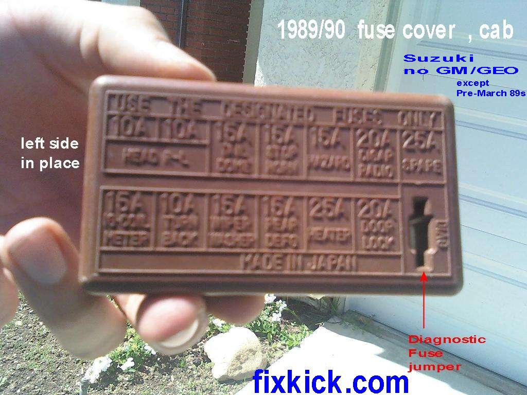 Photo 1, 1989/90 Fuse box above the drivers left
knee. Some early GEO fuse
boxes look
like this.
Photo 1, 1989/90 Fuse box above the drivers left
knee. Some early GEO fuse
boxes look
like this.
This Diagnostic jump pins set , activates the FLASH codes, to see DTC errors (Diagnostic Trouble Codes) ! 12 = good, all others bad news)
Some early Geo trackers were made (early 89) not at CAMI plant in Canada but in actual Japan and are wired like Suzuki's.
This is because CAMI started up production in early 89.
If the above fuse is missing?, that means, use the next 2 photos to jumper the Diagnostic pins. If you have this below connector then that is the one to use, in all cases.
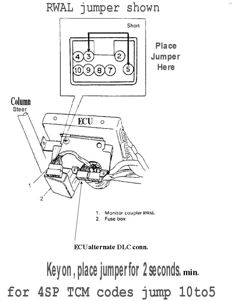
Related (DLC) are these old methods, for 4 speed trans and RWAL brakes.
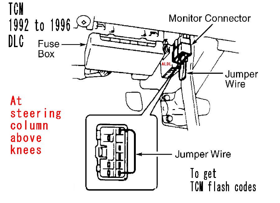
The TCM (transmission ) DLC is here. (92-96) (starting in 1997, PCM reports all DTC errors as, P07xx)
RWAL DLC: pre 96' rear wheel antilock brakes.
1991 to 1995 models only:
Rule #1, the Sidekick is RIFE with unsused, connectors for options not opted DAY1. Lots. So do no jump on the first connector found. but DO look at the wire colors. Blue-yellow is the correct wired connector.
This connector has a rubber cap, and has the blue-yellow wire.
Pin B is our flash code, demand pin.
DLC = Diagnostic Logic Connector, just in front of the battery. Some cars use the 6 pin.
The below a real RED 1991 2door 8v engine Tracker.
Jump the B to C pins. See if code 12 flashes, key on. and running. (12 = GOOD)
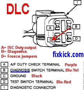 Do not cross over data plus and minus.
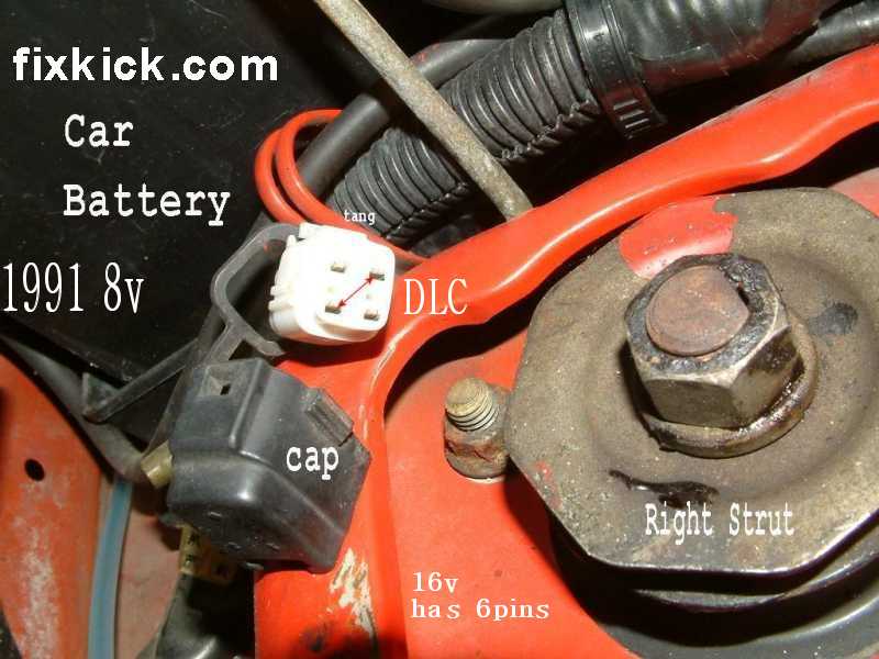 photo 2
After jumping B to C the CEL will flash 12 if all is well.
Freeze is the spark timing freeze jumper pins.
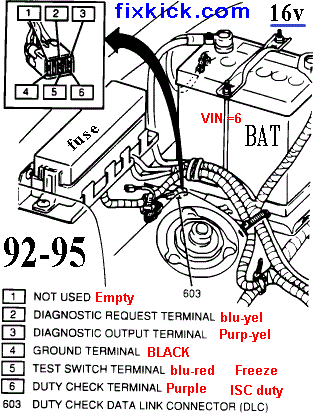
The 6 PIN DLC.
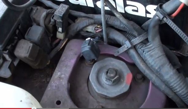
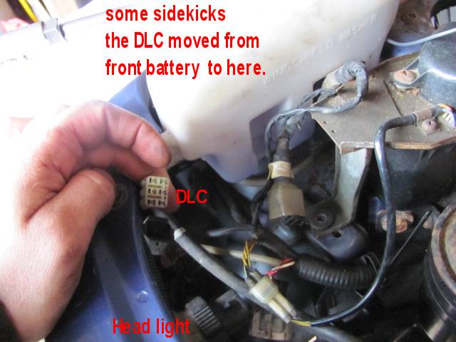
Below the Typical 16V Sidekick 1992 to 1995 (still next to battery these 4 years)
This 6 pin connector was moved to front right Head light shell in 1996.
All years with THIS DLC, use this 2 to 4 jump. SEE the NEW LOCATION HERE , a real photo.
Rule1 , all 5 pins must be populated or its the wrong connector.
The colors must match, See colors below.! See a real 1994 DLC here with rubber cap in place ,just yank off the cap.
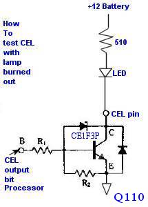
Pin 3 is the CEL lamp pin, if the lamp is burned out , this pin can be tested, with an LED and resistor to battery plus. (R= 510 ohms)
The KEY WIRE PIN IS Blue-yellow, seen on pin tells you it's the DLC.
Jumper 2 to 4 pins. See if code 12 flashes, key on. and running. (12 = GOOD)
(you can drive with this jumpered safely to find intermittent errors or while cranking a dead engine.)

After jumping as shown above, the CEL will flash 12 if all is well.
The 1996 to 1998 SUZUKI SPORT J18 1.8L SIDEKICK DLC looks like the connector above, and below, but was moved to the Left Strut (shock) tower . (left hand drivers side) used for timing freeze jumper only, and never for any scan tool.
All cars 1996+ (1998 = in Canada) have no flash codes for the ECU. (might with TCM in 1997 year and older) All 1996 , and newer in USA use OBD2 scan tools there are no flash codes starting in 1996.
Suzuki moved this connector 5 times. 89-2004
Photo3 , curtesy of "Cosmic-splatter". 1992 to 1995 is here. G16b engine below. (in 1996 connector moves same jumper connector to head light shell left ,near washer tank.)
 1992-95 example
The dang my CEL lamp bulb is burned out, and I just don't feel like ripping out the dash cluster today?
16valve engines have the 6 pins.
Jumper 2 to 4 (DIAG-mode) with paper clip, and use a test light or LED test probe or very very low current test lamp.
3 WAYS to do it: (6 pin cars; only) ( Volts, Lamp or LED) There is a 4th way with a logic probe, and 5th way, sure a resistor added here and a scope to monitor the pin also works, but both are very expensive, so I skip that here.)
The key factor here is the lamp burned out, means there is no voltage on this pin, so a pull up resistor is manditory to do the , the below tests satisfies, that need. (CEL transistor Q110 is open collector bipolar transistor {geekspeak})
The current must be limited to 0.10 amps or 100mA. (or the transistor gets hot, in the ECU, and nobody sells them today, rare parts used, maybe.....)
The first method uses the meter itself to do the pullup function (a simple trick). See the ECU guts here , the actual transistor..(geekspeak)
- The cheap analog meter ,can be used in Volts mode, 10-20vdc Scale, (a DMM won't work, if dash bulb is burned out) But analog needle meters do work here, with Red probe to pin to battery PLUS lug, and Black to pin 3 (swings High means flash, needle will peg out on 10v scale.)
- The stock CEL lamp is a GE # 18 and draws only 0.04 Amps (about 2x any LED) so don't exceed, 0.1amps. in fact, use a GE #18 bulb to do this test. (connect it from pin 3 , then to battery plus lug. (a lamp has no polarity.)
- I have my own home made LED test probe built up, from an old incandescent probe light,
I remove the old bulb (way too much current bulb) and put in what you see
below, with the resistor @1/4watt.(connect it exactly like below
drawing, Plus to Anode and Cathode to pin 3 ..
The LED acts as a pullup and glows for DTC flashes , this is by far the most safe way to use pin 3 , the resistor is Green-Brown-Brown, amd any %.)


The above meter, conneted inplace of the LED, (on 20vdc scale) will wag to show FLASH codes.. (using 12 or 20vdc range, Whats nice here, is that you are at one place , the DLC in the engine bay.
This cheap meter also excels for testing continuity of switches, wires, and connections, with its easy to see and read needle. (never use ohms in any live circuit or use amps in a live circuit until you learn how (in series with the load is the answer)
This (94') CEL (MIL or SES) lamp is what flashes codes. Example code 51 is a bad EGR. See if code 12 flashes, key on. and running. (12 = GOOD)

End: OBD1 technology.
OBD2:
DLC2 (above drivers knees at dash edge)
(there are no more flashing CEL scan codes, starting with OBD2 in the USA 1996 or 1998 Canada)
(yes on TCM 1996 only , the transmission has flash codes)We are doing only engines here.
You must have a real scan tool now. (all comments are USA cars only) The tool can be as cheap as a $10 ELM327 sold on fleabay or a nicer INNOVA 3100.
Starting in 1997, the TCM errors are now scanned here, now... (only) Tranny errors.... eg: P07xx.
OBD2 DLC2 above right knee. The Data Link Connector.


See this page for OBD2 pit falls... ?
Just having a connector above is no proof of OBD2 outside USA. Inside USA it IS proof.
1996+ all have it by LAW here. (EPA laws) We in fact, invented it.
The connector is never fully populated, (saves money )
Common OBD2 connections on early Suzuki Sidekicks, GEO and Chevy Trackers found in the USA,.
Outside USA is a whole other ball game (complex to the EXTREME) !
This section of my page helps you when the scan tool is dead, or gets hard commmunication failures. Especially old cars. If you want to bench test or hack the ECU, the below and my hacking page shows you how.
USA only and Canada starting in 1998. (this data was gleened from all FSM books on car. in print for G16B engines only)
OBD2 DLC connector (right knee cap, typical) Not all pins will be populated and is key to seeing what you have. IN AND OF ITSELF, THIS CONNECTOR DOES NOT PROVE OBD2 COMPLIANCE !| OBD2 pin # |
Signal or Function Name. |
Suzuki Sidekick 1996 |
Geo-Tracker 1996 |
Suzuki Sidekick 97/98 PCM year. | Chevy Tracker 1999 to 2004 |
| 2 |
Data plus comms. |
E34 PIN 17 (ECU pin) |
n/a |
E175 pin 6 (PCM) | n/a |
| 7 |
Data K-line comms |
n/a |
E33 pin 22(ECU) |
n/a | PCM/ABS/SRS scan comms (and Grand Vitara's too) {E61-p25-PCM} |
| 8 |
Mfg, custom pin |
n/a |
n/a | n/a | RKE Remote key Entry FOB prog. pin (jump pin) (not on a Suzuki) |
| 4/5 |
Ground |
Battery minus |
same |
same | same |
| 10 |
Data minus , comms. |
not wired, PWM |
n/a |
E172 pin 17 | n/a |
| 16 |
12vdc for scan tool POWER ! Dome fuse ! |
Battery + plus |
same |
same | If your scan tool is dead, this be why, the DOME fuse is blown. |
Even if the scan tool has its own battery, you still need +12vdc at PIN 16 ! Check all fuse box fuses carefully for missing or blown fuses.
The scan tool can communicate to the ECU just key on ,not started. (some 1996 cars you can't) but our cars and all newer cars you can. This allows, you to see old stored DTC's and see sensors that are active (ECT/IAT/TPS )
All facts on this page ,are of no importance with new scan tools, the tool finds these pins AUTOMATICALLY. Only hacking or bench testing ECU's or using very old scan tools, (circa 1996) is this a question.
My Innova 3160d works on all cars above, and for SRS and ABS, in some cases. (and my JEEPS and many other USA cars , see lists in link to left .)
The DLC pin 4 on the Suzuki is chassis metel ground., pin 5 is battery direct minus ground, also called quiet ground, in the electronics world. Body metal ground is very poor.
I've seen some cars and scan tools missing pin 4 or 5, what I do , is add the pin if missing. (either) (a rare flaw, but devastating to many shappy cheaper ,scan tools) There should be 2 pins, here (4&5)always.
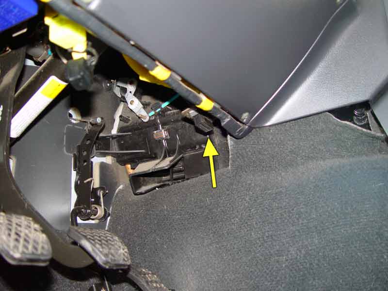
Below is the OBD2 DLC #1 under dash on all Sidekicks and trackers 1996 (first year) up. Using a flash light , you will find it !
Watch out for kid hackers. that buy an OBD2 meter, or gauges or what not (nanny box for insurance company), then move this connector up in dash hidden and with an extension cable. The car came like this, below ! (on that edge somewhere)
PHOTO OF ALL ODB2 ECU DLC#1 connector: (there are no flash codes starting in 1996 USA) somewhere along this edge is the 16pin female port.
Next it the 1996 to 1998 DLC2 (for freeze timing.) (the suzuki SPORTs this connector in located on the LEFT drivers side strut tower) again, there are no flash codes, starting in 1996.
Last is the TCM , DLC 1992 to 1996 only. (code 12 means , TCM OK and happy)
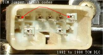 This is jumpered to make the OD lamp flash codes. TCM is covered here.
FYI:
IGNITION TIMING SETTING:
The test switch terminals are the Timing freeze jumpers (to ground)
This page above, does not cover RWAL (brake) jumpers or 4speed TCM tranmission jumpers, look here.
ver 6: 8-5-2014 added 16v real photo #3