Are you wanting a good scope and don't want to suffer the horrors , of old scopes (to me it's fun , the restoration)
See this under $521 bucks.
If you need a great low cost scope, and don't need vast band width , a new scope , see video of it.
Me: (retired at 61 early)
I am a retired "Electron Pusher". In 1974 (fresh out of Viet Nam
 ) I worked fast Integrated Circuits with TEK 7904s at Intel.
Worked for 3 major electronics companies in Silicon Valley and then Philips now NXP.com
I spent my final days with automated controls. PLCs and more complex. (x86 assembly lang. , "C" an Pascal programming too)
I think the 2430 was one of the first ever Digital scopes, it was near impossible at that date, to do that, but TEK pulled off that magic.
My Old Tek 2430 has the Acquire button, so that anyone can get a signal up. (I guess Tek invented that idea?)
Using the Motorola 68k microprocessor,.
See my 2430 review here.(and diagnosis of it)
2430 failures?
Working with out a scope is near impossible, for the serious problems we face.
Electronics technology is very diverse. (DC to Daylight as we call it)
No one scope does it all, save a few $50,000 scopes (maybe) so pick a scope that matches your needs
This page is to do real repair work for testing, not just school practices with a cheap $20 function generator.
We wish to find real problems in real gear. (in my case is , all MCU appls, PLCs or other old slow controllers)
A scope can be setup to measure voltage over time (X/Y) V/T or current over time, I/T (I= current) using a simple current probe.
To use any scope, you first need to know what to expect. What is the signal.? What is the shape?, what is it doing?
What are the rules for this signal?, lacking that , the scope is near useless.
The answer to that is easy, read the service manual for the system under test. (or the chips themselves)
The Scope can find very easy, the following problems, in circuits:
- Noise. Lets say a too high ripple noise in a DC supply. (or in vehicle, noise from the Charging system ,etc...?)
- You can Check all analog signals, up to the bandwidth of your scope. Yes, chips come in Analog, digital and hark, Both.
- Digital
signals too weak, not going low enough or too high or shifted to
illegal bounds. (VIH/VOL, VIH and VIL) or gross over shooting or even
Latchup events.
- Like the below, my CKP signal must cross zero or the
ECU will not see it. A bad connection can cause that. (damage
sensor, or no power to the HALL)
- It can see bad grounds , at sensor inputs, we call this
ground bounce, in digital signals. Cars, for example have
HALL sensors that need good grounds and power.
- When using a DMM volt meter, it averages signals, (a kinda lie) and you miss out on what is really happening. The scope shows real time signals.
- On more expensive DMMs they do have capture Min /Max but is
very limited in accuracy, it only works for slow signals. (slow sample
times , misses most glitches)
- My storage DSO can store, just what happed last. (you
can capture signals that are rare or catch an aberration for analysis. ) Finds Fast nasty Glitches.
- The Scope shows you the truth. (in all its glorious bandwidth, like watching 3D TV the first time)
- In ever case, of unsolved problems, my scope and my analog data logger , found the cause. Every time. Newer scopes have the logger built end but are $$$.
- By Glitch, we mean a fast moving, illegal, voltage or current aberration, Glitch is easier to say, no?
- When
after working for 50 years on problems, this list above is very
short. The Scope can do MORE, lots more., with current probes,
more.
I have set up this scope to catch glitches, that are very random and it will do the job.
You can arm the trigger ("Single Sweep"), and wait for the signal, and BANG. Practice and you can too. The trace will die away, but you saw the glitch.
Hard pressed one day ,we used a camera (lights out) , 2 guys to photo that 1 time event."Polaroid" (we didn't have the storage scope , very expensive back then , late 80's)
The real DSO scope is the far better one, to do the capture and look, after the fact. Like my 2430.
In the world of electronics, not all problems are simple , like DEAD or inactive. Not all problems go away with swaps and guessing and parts swaps.
For reality, you can in fact get noise. (bad connections , ground loops,etc)
I have seen circuits cards fail, in fact, a specific chip on one board, caused by a noise being generated, far away on some other board or device in the system.
Only a scope finds this level of problem.
If doing development work, (test jig, prototypes, breadboarding, etc) you also validate your signals, using a scope or for doing debugging of a new design.
Now my 2 rebuilds: (back in the high life again...)
I love my Tektronix 465, (1979) it will last a life time and allmost all parts inside are available (or easy to substitute ) this scope has mostly Transistor scope. Discrete.
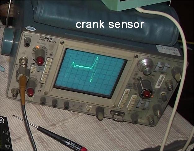
Below, I'm making sure my signal CKP , actually does , zero crossover, so the ECU will be HAPPY! No scope. no joy.! I'm making a MPG gauge here...
 S/n: B235xxx
The Tek 465 service manuals (free PDF, are everywhere)
The are examples of how to make perfect schematics, the likes of which few makers of anything, understand.
It's the high water mark of QUALITY. Both product and documentation.
Many makers today, offer no schematics, All a big secret. They can't give away their , proprietary circuits, not like the old days.
Can't blame them, with China clones or worse counterfeiting, My guess, is TEK is winning, Bravo TEK. Do win, do employ American workers and innovation.
See my Tek 465 slide show. (bought in year 2000) My old 70' Military surplus scope died, no parts avail. RIP.
My TEK , is a $50 scope from the TeleCO auction. $3500 new.
Rebuilding the 465:
Actions taken:, C125 shorted, in 2007. I used a new Tantalum Cap. then C302 failed too. Tant. fails are rare, the electrolytic, do not last forever.
The Vertical channels:
I now found 3 X1 and X10 lamps burned out, (1 was good) ( I used 5v rated green LEDS here, no resistors at ALL) Wiring in Resistors here, would be a horror.
Do not solder for more than 1 second or the weak plastic melts in the lamp buckets , see photos below. !
The 2 main screen Graticule scale (scale) lamps. were replaced with white LED (2v) are in series and 1x 220ohm resistors) (no 5v lamps at mouser in white)
The Graticule scale mod works, just by replacing Lamps with LED , 2 LEDS wired in series, then I added a 220 ohm series resistor, the stock scale driver , transistor ,I had to remove the transistor and jumper pads E to B on the Q1570 socket pads. The max current is about 15mA. tiny now.
The POT can drive. the low current LED's just fine. 0 to 7.5v is the drive,via the front panel POT. max .07watts way less that 1/8w total.
The 1x/10x LEDs , the S/N B250xxx and newer scopes, work perfect , early scopes, need the B250xxx update for the X1/X10 transistors. (simple, see the schematics)
Next actions completed:
Cleaning:
While doing that , clean everything with IPA (91% Alcohol, never rubbing type). and used special electronics spray on all Pot.'s and Switches, reward?, all came back to like new life.
IPA means isopropyl Alcohol.
All switches were gummy, flush and clean as you cycle them, it's very easy to do this. (using switch cleaner, plastic safe)
One of the best things to do, with a scope #2 is SCOPE out, it's LV power-supplies for excess ripple, the service manual covers that, no need to show how.
LV means LowVoltage, HV means the CRT HIGH VOLTAGE sections.
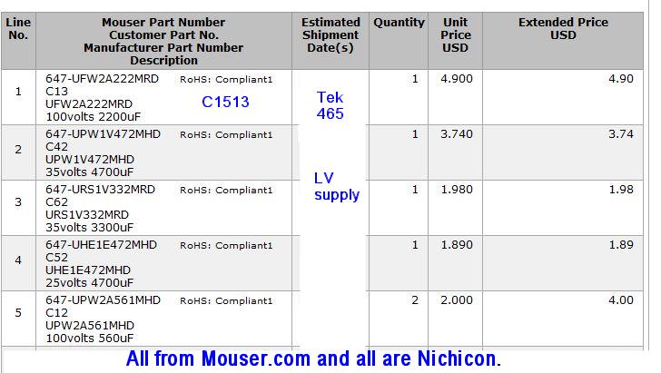
On my TEK I shot gunned it out, with all new top brand, low ELECTROLYTIC ESR caps. from Nichicon (japan) I never touch tantalums ,they are long lived.
Plan on replacing the electrolytic caps. I replaced all the LV Power-Supply caps with Nichicon's (a top brand)
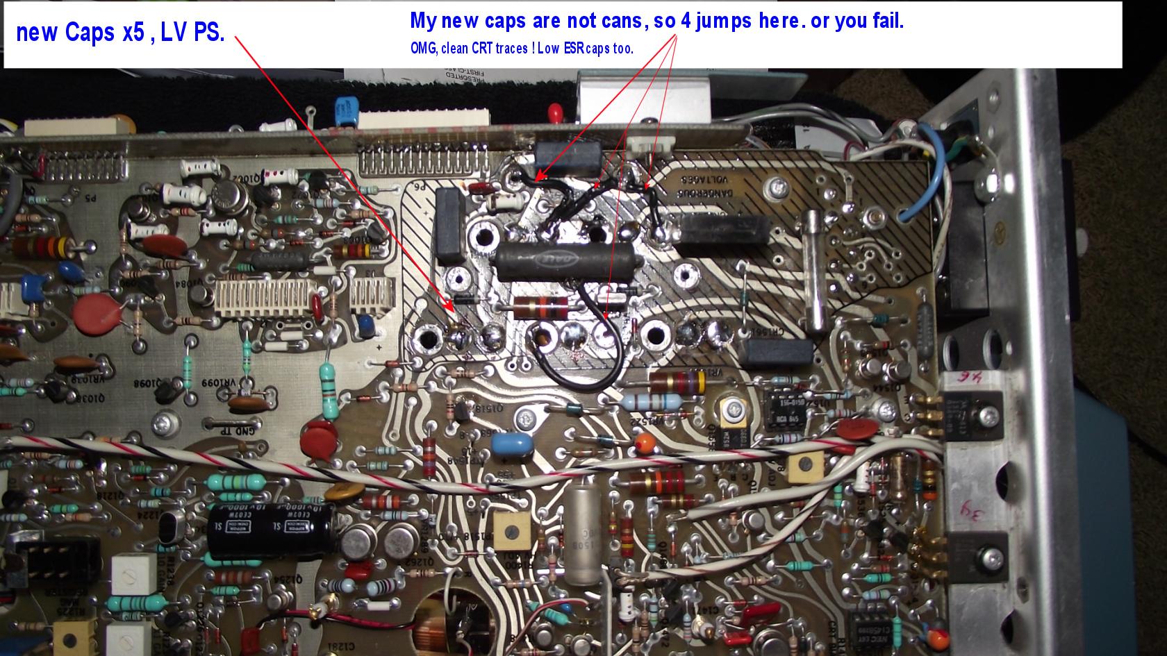
See this photo, for the magic jumper wires, at the Large CANS (gone) triad ground pins. The Caps from large jumper bars , that my new caps do not have.
This gets ripple noise, to a minimum. Especially on the 5vdc and 15vdc buss.
When the cap's were done, the scope trace looked factory new. a perfect flat clean in focus line, at all times. Nice. $15 cost.
I next did the full Vertical channel calibration in the manual and get stuck in the trigger section. 6-24.
CALIBRATION:
I only calibrate the things I need to be accurate and stable., Vertical gain and trim, and trigging, ( I did not attempt horz. freq fine tuning, $$$)
I don't need dead nuts accurate time base, with this scope. but does very well.
The SM , is targeted to the PRO Calibration shops, with their fancy TeK CAL rack and 11.5/-33v power supply. You will never have that , I bet?
So, what can you do, answer, lots ! Use a home made Signal Generator, and a DMM tool and a DSO to do all setups.
BNC cables, pads, and terminators, are dirt cheap and I have most of them are are BNC "T"
Do be aware the RF fitting come in many characteristic impedances, 50, 75, 93, 600 ohm, (we use RADIO PARTS) not TV, NOT CCTV, NOT TELCO.
Rule 2, if you mismatch fittings, you will get harmonic noise and the tests are now FUBAR.
One trick I use is, to take my very accurate DSO scope and use it to set my cheap crappy signal generators outputs, to an exact level (tedious but saves $1000's in correct gear)
I do not have the TEK CT-3 SPLITTER , I had to make my own splitters (all major maker of these parts sell these tools) You do not need a CT3.
Then used my good DSO to set my cheap generator correctly.
The below drawing is my best hack, at decoding the words in the book.
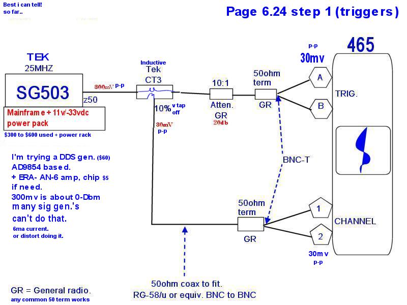
I made a drawing the best I can for calibrating the Triggers.( reading TEK SM words"service manual = SM)")
My 465 scope does in fact fail, step 6-24-1e (the first 25mhz 30mv test) for triggered ! But I corrected this.
The Factory SM, is weak , only because they ASSUME the shop has all TEK, calibration tools on the self. Those weak words are.... page 6-24.
This chapter 6 setup, needs a powerful signal generator. (0 dBm) power full, at 50 ohms. 25-100 Mhz Sine wave (clean, no harmonics allowed)
I did find old Sig Gens used,, that had clean and powerful output (but is not calibrated) I used my DSO to set my cheap GEN to exact values, (I cheated)
The next checks are with a real RF HF SIG. GEN.
RF ! Radio Frequencies... the real deal.
I don't have nor ever will have a TEK SG-503 and power rack. The HP 8648 used, is one of the best buy's.
NO 503! This puppy puts out 0-DBm (300mv) into a 50 ohm load) easy, Grab 100 , cheap Gens off a shelf and they don't cut the corn.
No lie the 503 is the way to go, it works perfect. (saves time and has stable out puts, making steps shorter ! , this is clear.
So what are the DIY ways? (say under $100 bucks) below that , you need to just skip all this.
You need a clean 100Mhz RF Sign Gen. with 50 ohm grunt. 6.0 mA drive A.C min. that is what you need. 300mv p-p (peak to peak) or 0 dBm levels @50 ohms
RMS that is 212mv (my new Tek scope cursor shows RMS, values , so there you have all 3, 300/212mv-rms and 0dBm)
The correct output using 20Log(10) is 0 DBm, 1mw , 300 mv. if your GEN can not muster the energy level it's a bust.
Signal Generator or as we say a GEN.
The SM (service manual) calls out slow Square wave, I used this. easy.
For the Slow Square waves , I have this USA chipped, but PCB card china made , by USA comp. AD9854.(I bought the card naked and built it up to my needs)
I will not cover DC inputs, anyone can create a noise free DC input and use a DMM to set it. (use a bench quite variable power supply or batter and POT)
Solutions ? HP 8648 used, is one of the best buy's (or a cheaper model and use a good accurate DSO to set levels on the dime)
- To get all RF frequencys, you can by 2 SIG Gens, cheap. Same with low freq. use a cheap function generator.
- Clean RF , (no harmonics , only a clean SINE wave)
- Stable output. No drifting, like cheap Sig Gens do. This is show stopper, if unstable.
- 300mv over 50 ohms min.
- If you need DC offsets, figure that in to your needs.
The HP generators are good.
HP85xx series like 8640 can be had cheap. (best of best at beat prices)
8601A does 100mhz.
The best source to find one is a HAM swap meet.
Or beg on Craigs list lke me.
Chapter 6 , continued.:
First I got clean , RF and at the correct levels then:
I used my new scope to SET THEM. ( no autoleveling GEN requires this new step)
What I did, is make my own 50 ohm terminated signals the hard way, using accurate instruments, my 2430 is that instrument. and I just forced the correct voltage in to the
465 with a 50 ohm terminator attached, this is clear, on page 6-24 in the real tek service manual. linked here.(free from TEK ! Thanks TEK !)
I have orig. hard copies of all books.
My 2430 scope shows the (cursors) as 212 mv RMS (x1.414 is 300mv p-p). now. (took some work)
This will allow me, to get my scopes trigger amps, all tuned and working spiffy. (mine are ALL messed up. Channel 1, but not channel 2)
The only way to fix triggers, is to do the Calibration, and then fix the steps that fail. (even the SM states that fact, in trouble section)
I'm all done rebuilding my 465 , just finish the Trigger, calibration. This scope is still popular. Analog 100mHZ, easy.
My 465 is ready for 20 more years. (end 465)
My newer Tek 2430 (1986), 2013, purchased, a real DSO digital scope. S/N 0116xx options IR and 11.
I have 3 free manuals here, both are OCR rebuilt (allows searching; try "Trigger LED") Tek allows me to source them. (relics, only)
The Original manual: (now searchable)
Version A:
The Military manual.
A joy to own, it is like magic having one of the first DSO every made. (and the intelligence inside , wow from 1986)
Unlike new DSO scopes, that convert the analog to digital at the 1st , 5mm distance behind the front BNC, connector, but this scope, runs the analog levels deep inside, all the way to the CCD array.
This CCD (charge coupled device should say Analog Charge Coupled Device to avoid confusion with CCD digital serial memory or CCD camera arrays today.
The CCD has ERRORS is the storage of this analog charging and shifting ,end to end ,so the Factory level CALIB tables store these, offset errors in NVram, the lack of which make the scope , near useless.
The CCD then Feeds the MAIN A/D converter, analog to digital.
The remainder is all 100% computer data processing, "SOFTWARE, or better named FIRMWARE"
See scope repairs here.
See my slide show?
Was $8000 new (MSRP). and this is all a big laugh to those with a new FLUKE 190-502 5 GS/s , at $5000 MSRP each. Or new TEK scopes.
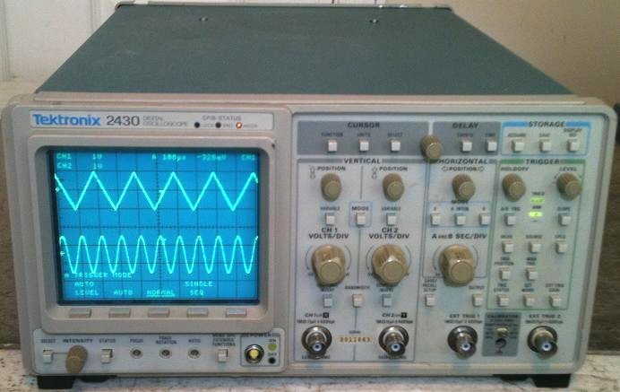
This photo to the right is my TEK scope PASSing Diagnotics .
I have OWON 7102 DSO too. new.
The comments below, in the REBUILD sections, are hands in side the scope, are with the power cord removed.
Plus stay out, of the High voltage section and CRT leads and there is 400vdc in the left side of A16, TAKE DUE CAUTIONS.
That is a Cathod Ray Tube and NOT some LCD screen.
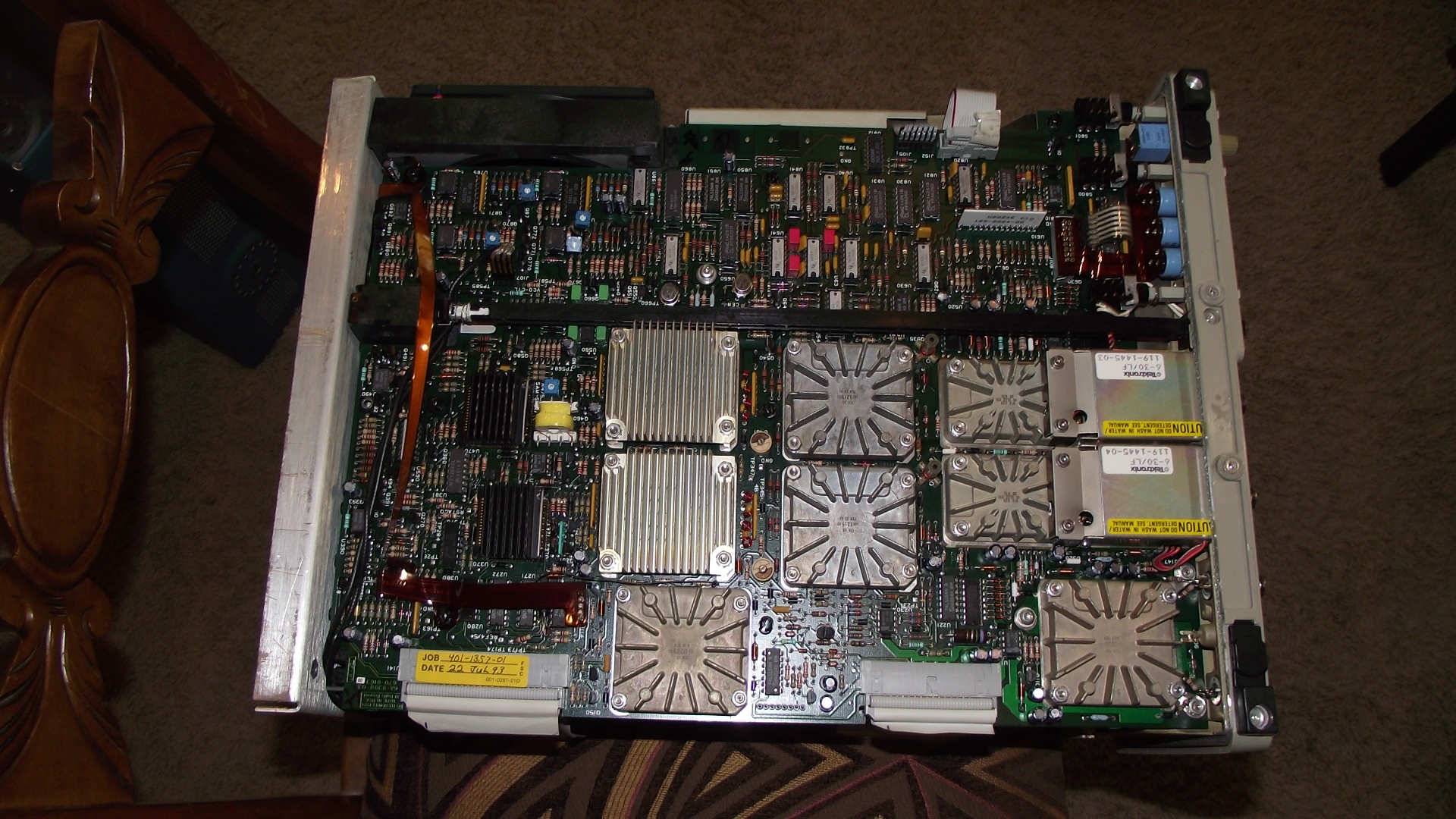
Looking deep here, you see one of the only fully documented DSO scopes, unlike to days secret designs.
They did the near IMPOSSIBLE back then... !

This next photo is just showing how nice this scope can present an asymmetrical signal. Impossible to do on my 465.
That gap causes my 456 to crazy, A new DSO will suck it out like a blood hound. Me , I roll the horz knob and bingo.
 CKP simulator, I can see 36tooth .
The above signal (crank sensor) is what goes to my OBD2 TEST Engine controller. (my simulator) I can see the 36 the tooth gap in the tone wheel.
This DSO scope, THEORY: Jump to Refurb all this is boring.....
See my slide show?
It's an amazing scope for its time. but has MANY proprietary TEK hybrids, inside that are near impossible to find. Pray they never fail. (CCD/PreAmps)
The scope is a "vast play ground, of real TTL 74xxxx logic chips". (begging for a FPGA, to drop by, for a visit, LOL!) Plus lots of 2016 RAM. old 2k x8 (dinky)
The only thing bad, about any DSO scope (all?), are the non second source-able parts inside , those finned aluminum plug in analog devices !. (keep them cool at ALL times)
Do not block vents. (bottom , top, or sides ) do not run the scope flat on a blanket or pillow or anything that blocks any vents.
Sample Rates:?
100 mega samples a second. (sad, by todays standards,huh?) 150MHZ bandwidth, and 2nS trigger ! + boot up, autocal...
This scope has a connect the dots button (on/off), (bottom left , select + vectors off) now that is fun to see the live digitization from dots to waveform about.
The new cursor feature gives you a free DMM (volts) and free Frequency counter, horizontal. Amazingly accurate too.
Do not buy a old digital scope, until you are happy with Aliasing. (newer scopes solved, that 99%) Faster sample rates, allow smarter wave form recreation.
Nor for radio work. (as Hams say) (you will be unhapply with complex wave forms that are Fast) But will be ok with SINE or square waves signals.
Learn how to detect Aliasing Look up Nyquist sampling rules first the 2x rule.(read the Tek manual for how this old scope deals with that limit)
Unlike any analog scope, this scope is....a Digital Storage Scope: "aka DSO, scope or O-scope"
This device below has a Brain, (Motorola 68k MCU) that only knows, the existence of different types of wave forms, a Sign wave is but 1, how about a triangular wave, or square wave) (newer scopes are , yes, smarter and faster, even giving RMS values on screen) I am ignorant of the true waveform processor inside, but it does great magic , considering how old this scope is.
We old schoolers, know how to do the times 1.414 or .707 to get RMS. 120v A.C. is 170 p-p (as seen on scope) RMS = Peak x .707.
The newer scopes do this simple math for you. (peak or RMS or peak to peak)
Evolution:
This scope digitizes the analog , and on the newest scopes $$$ ( the input is digitized just 1/8th of an inch, behind that front BNC (British Naval connector).
At the front panel this happens, so the ANALOG world goes bye bye fast, on the newest scopes. (from there on out, it is all Digital , until CRT presentation, yes the final output is again, becomes ANALOG, again 2430) (on any new scopes they have LCD presentation, and that stays digital, end to end )
The new scope have the A/T burried inside the BNC connector and seems to the average joe that the BNC sendes out a digital stream, of data, in fact, it does.
On new scopes, there is a total devoid of internal analog , anything. (a goal for sure). ( and is vastly more simple as result, no more rare analog AMP chips ,deep in side. no more OMG, Analog CCD)
Keep in mind, no analog scope, can do 33GHz bandwidth's like todays DSO scopes, thus the need for digital. (and many other cool things too... storage, etc)
Theory of operation: (skip this, part, if old hat)
On this puppy below the 2430,
For sure this scope is packed side to side. SARDINE CAN, like, with tons of TTL 74xx chips . ( something to behold one time and appreciate Gate Arrays', etc.)
It is fun seeing how in this era 80's , doing a Digital scope at 150MHz was near impossible, but they did do it. (what an effort ! and what a boat anchor !)
The CORE:
The core of the scope is the SAR, ADC. Successive Approximation Register (Analog to Digital Converter or ADC) this is the main digitization device.
The logic inside, digitizes, the signal into 1000s for voltages and stored them.
This was done using a fast for year 1985?) ADC. Part #TDC1001
An off the shelf ADC by TRW , is 22.5MHz clock max.,or a total 400nS conversion time chip, No flash converters in the 80s.(ie. parallelism).
This TEK chip, might be faster.? My guess, is YES. (its a TEK version of the origional , my guess under a Tek/TRWCONTRACT buy)
Tek may have special ordered, 30 mHz ADCs then.... I don't know really. But if bad?, good luck finding one,
The Front end:
The Tek 2430 (see page 356 in the Service Manual, SM has 520 pages!) the signals (analog input) pass deep in to this machine, before it hits A/D.
In fact, it passes to 4 sections DEEP.
Example: (BNC, means Britsh Naval Connector) The below is a simple path in ASCII. (ah, text?)
(BNC Ch1> U420(pre-amp) > U440(peak-det) > U450 (CCD) >> (ADC) the ADC converts in about 400nS. see chapter 3 in the SM for the full story.
The peak-detectors sample the min. & max. peak levels, found at each clock cycle, (at 3 bandwidths, 30,50, full MHZ), so at this point just 2 analog signals are sent to the CCD.
(this is a serial, large memory this analog CCD, a giant analog FIFO, first in , first out) In the old old days, Ham talk, bucket brigade style.
This CCD is critical, it runs hot and must not ever be allowed to over heat. They are extremely rare devices, do not stress your CDD with lack of air flow.
This analog signal is differential ( that is, a 2 rail sig) now (out of preamp), to maintain very extreme accuracy, all the way to the CCD and to ADC. (this method cancels most noise)
The CCD:. ( a large serial analog memory) (not a camera array , nor serial digital memory)
It stores, 2 analog numbers and shifts them down, this FIFO like device. this device CCD buffers up (memory) 1024 analog samples, then shifts them to the slower, ADC.
FIFO means, first in, first out.
The CCD can switch to bypass mode and send live CCD input directly to the ADC for slower signals (triggers) and is called the "short pipe line". cool !
In this mode, the CCD does near nothing and the ADC flash converts in real time. (almost) my guess? is about 30mhz? band width is near live conversion?
It's fun to see the compromises going on inside , in 1986.
The CCD is just a memory full of capacitors, each one stores and analog voltage. (a camera CCD is kinda similar) but this device is custom and is not photon related at all, only charges are stored in a bucket brigade ASR fashion, shift register. It's a mix of ASR and digital logic, It digitally shifts analog stored charges. Analog Serial Register.
The makers call it CCD ,a charge coupled shift register, "CCSR" (or analog shift register)
I like to think of it, as a cascaded chain of ,sample and hold, circuits. Sample and hold is a basic, ADC design function. (analog guys)
Next, is the conversion section, Analog to Digital. (it took a long path to get here, unlike all new scopes) for sure, this architecture is dead tech. now.
Trick 2: (#1 was the "short pipe line")
This ACD pre circuits,do a 4 way , min/max old /new compare before converting. (see SM p357) This helps in the speed of conversion.
(it does skips , and those save TIME) (less than?, same? or greater than? logic decisions) I think it skips for non greater or equal...
I mention this theory only, so you know how it works and why odd things might happen, at the 3 bandwidth boundary's (30,50 and 150 mhz) {know your tools and limits}
Near the Nyquist limit (2x):
The Motorola 68k MCU Brain, may look at these vast numbers of voltages in TIME, and decide what wave forum it is. (the analog processor, the 68000 code must do this...)
They do this because the sampling rates are bad. At fast rates , wave plotting is easy.
If you have vast digitization's per transition, then this is easy, it's a direct plot, but if only 2 points. you need magic to guess at the waveform on CH.1.?
The scope will in fact mess up, if it sees a rise time, but no fall time. Say, you ran out of horz memory. So it shows a Alias. On mine , I get funny spikes.
Next, it then connects the dots, and plots the signals on the screen. (a fun check is to generate a very complex waveform and see how well this SCOPE , reproduces it )?
My wild guess, is the MCU (ucode) looks at the signal slope. ( near instant fast rise time, is a square wave, linear, or maybe a, triangle, and sine rates, are a sine wave)
How this is done?, the order and the methods very, by all designs and makers of scopes. I'm sure their little secret. But fun to test out.
To be sure, they all do, capture/convert input , storage and presentation. How that is done, varies by year and makers. Today a big secret.
What happens to day, is nothing short of amazing, near magic.
All you need to know , is it's not WYSIWYG , it's not an Analog scope, (What You See Is What You Got") What you see, is BIG TIME processed. OR JUST PLOTTED.
What you see is not real, what you are seeing is and interpretation of the actual signal. (but less so , today, due to rapid advances in the technology)
If you are happy with that, then the below device many be useful, to you.
Keep in mind, the below scope is a DSO, "storage" you can scan and look at old signals and then examine them later. this has GREAT POWER.
(in fact a "supercap" inside stores your readings (save feature) , for about 3 days)
This scope has a "superCap" make sure it still works too. (the 3 day device)
end my theory of Op's:
MY REFURB: 2430: (and some diagnosic checks , if needed and some repair hints below)
See my slide show?
Rule 1:
Do no run this Scope, with the Case cover removed, with out a 12" min. External Fan blowing on those many bottom card heat sinks!!! (or it will melt down, and that is the END)
See those hot chips here custom analog heat sinked chips
Rule 2: Do not run the scope with card A11 J100 removed or you will burn a hole in the screen phosphors. That also means, running scope with A11card, disconnected.
In fact pulling many connectors can do this burn up trick (I'm too chicken to try them all, as my scope runs like new)
To be safe, killing sweep generation like that, remove the A17 low voltage plug first. (lower left corner) P/J176
Rule 3: if getting your body near high voltage of CRT, unplug P/J176 (A17) BE AWARE that kills the fan too. -12vdc is fan power.
For sure I blew out all dust inside, with low pressure air (9 PSI book says) then cleaned all dust off each heat sink. (the latter , mandatory basic service and is in the SM book)
Hard Failures.? Diagnosis for dead screen or dead processors:
I made this section for other persons, emailing me for help with specific problems.
Fuses, for sure check that out first, there is a small hidden fuse on the A16 card that if blown , makes the screen dead. (as does other failures)
The good news is all failures can be fixed , except, the heat sinked parts and VTI U670.
One could find a bad scope and cannibalize it. All the TTL logic is still sold and the Dac10s and the TL0 analog chips. (in a word, all small chips)
The real factory SM book: (one of the best books ever published on a topic, as complex as this) Down load it and safe it. It's Free.
The Service Manual PDF is here. (30 mbyte size) (commented battery issues , and power loss issues "OCR searchable too !)
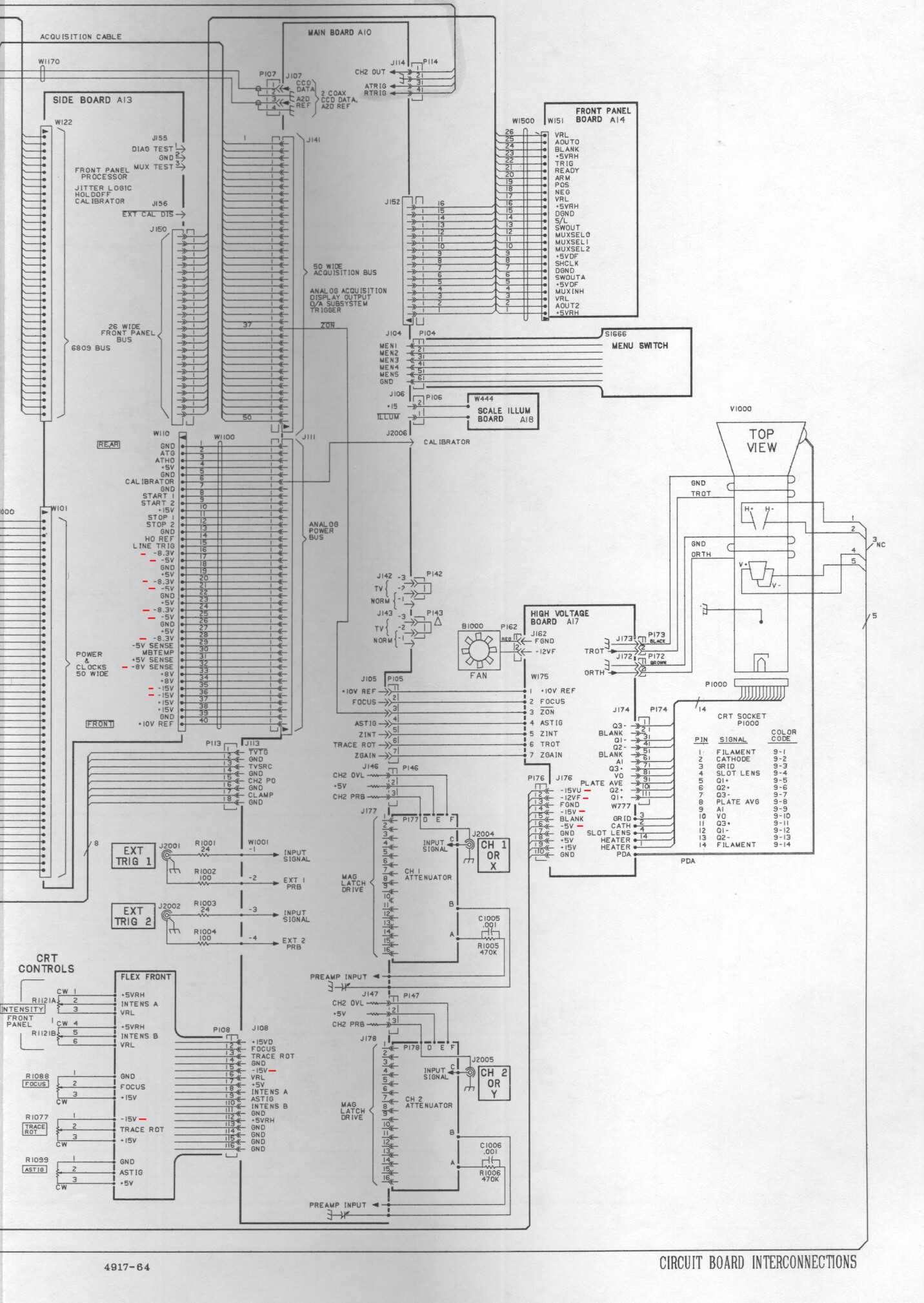
oops this page in the PDF is blurry, see these 2 pages, 200 DPI resolution Intra-connect A and Intra B.
The only weak spots in the manual are lack of good DC power distributions drawings (or PCB fab drawings , so we can see them all)
In both photos above. I marked every negative supply with - the PDF manual, it's hard to tell minus from plus.
These 2 pages Intraconnect show where all supplies start (LV or HV cards ) and all loads.
Today I leaned that when you unplug the A16 (DC power) Card, you break the 2 grounds, called, DGND and GND, (digital and safety ground).
That means if testing other cards, for power shorts, you need to terminate those 2 at the card under test. << secrets
Hard failure like dead screen, or diagnositic errors? I tried to help with the each class error below.
- The CRT Screen is dead?
- Diagnostic screen , errors? 1000, 2000... etc? Do the relays inside, click as it boots up?
- The Trigger, Ready, ARM, Plus, NEG. LED flash funny codes?
- The same LED are stuck on, just one and flashes but is not code. This and the above is covered in the book.
- One supply is dead, or the -15v is dead causing the others to be dead (normal that later)
- One card "PCB" is shorted? A power buss feed is shorted? PCB means Printed Circuit card.
- NVram failed. or its external battery or its internal battery?
(see page 37 block diagram part 2 ) all pages refer to this book here.
The Pages to read first are about boot diagnositics. Chapter 6 page 27.
Then Page 6-34 failure logic table , if not signs of life then see Procedure 8. on page 6-93 CALLED dead start checks.
It tells you to check all supplies (D.C. power) first. This scopes power supply converts 120vac to 400DC first, then many other supplies next.
The scope will not run with any DC supplies bad. If the base line DC supplies are good the digital signal called, DCOK goes to TRUE state. (logic)
If DCOK fails, the scope will flash error codes. (that is, if +5vdc is still good, processor power) << no magic
System Diagnostics. (on board diagnostics one of the first systems to have it !)
The IS THERE LIFE test, is in the SM book Check all LED trigger errors and the GPIB LED set, first, if screen is dead. (the LEDs talk to you, by flashing errors or are DEAD)
If the LED's send blink codes 6-28 and if it can't blink codes the trigger section just blinks dumb like no code. this too has meaning as does dead GPIB LEDs.
IF the trigger LED's act dumb (oddly) (bootup flashing is dead) or do not flash out codes but in the stead, they just blink with no code, that is shown on page 6-94 (flash but no code page)
So lets say you expect a bad power supply.? I have updated my slide show , so you can see real photos of the TEST points (side card), and how to access the LV card. (low voltage supply)
The steps to TILT up the top board is shown in the slide show. The 2 cam locks (plastic) are real tricky buggers. (go easy there) The last chapter in the SM book shows this too.
Yes, you can run the scope with the top card tilted up and fans blowing on the bottom side (I use 2"x4"s (wood) to get a path under the scope for air flow) Think about how to do that!
Before working an any scope, we check that all supplies are in spec. (or the Calibration can and will fail)
The supplies (some are load voltage sensed, (kelvin connects) and must be terminated. (at one end or the other)
( These Supply sense lines do have 100 terminators, to allow open loads, but do be careful)
If you have, "Is there LIFE" failures (in the book tests) the first place to measure power is here. The A13 card (right sidecard) check them all.
If some are way low, they are bad, so the next stop is the LV supply, well buried A16 here, after tilting up the top PCB board.
There is a well hidden fuse on the rear right of A16 behind that fat ribbon cable. (must read 0 ohms with any resistance meter)
The slide show, shows the way to get there.
If you need to go deeper to the front UNREG side of the A16 card, the metal cover needs to be removed. Warning 1, there is LETAL 400 vdc under that cover!
A dead supply is easy to find, just don't touch fingers there, as you are doing LIVE testing, and probe with meters and scopes. (yes , it may take a scope to fix a scope)
Any short on a supply bus, will cause that regulator to shut down. (via over current and heat sensors inside the IC, that does this regulation)
Connect the meter, (using ball clip leads) then with hands out of the scope, turn it on (hands free and live) <<< safety101
This is standard proceedures working on any High voltages. (or near) Anything over 36v is high voltage.(UL rules)
If you need help?, ask on my forum.
All comments below are from the above book and exact PDF pages, (adobe reader page numbers) or in this fashion chapter 6- page 27. 6-27)
The scope if it fails, the boot up Diagnostics it flashes the Trigger LED in a binary sequence to tell you, which test fails. PDF page 208 shows you how to do this. (the 8 steps)
PDF page means Adobe reader page number.
This scope must have 2 running processors (main +display) to flash those codes (read, has some smarts) See PDF page 205+
In most cases the flash codes work , if you have a working +5vdc supply inside. (A16)
If the Scope is dead, see page PDF 214, See photo 2 here, for a normal screen.
First check the Trigger LEDs, and if the scope has GPIB option it too can help with the diagnosis, in fact, you can scan the SCOPE using the GPIB bus. (say with screen dead?)
They will mention GPIB (IEEE488 std.) this is a standard parallel commumications port that has vast features. (RTM read the manual) and has LED status lamps to watch.
Those GPIB LED are at top right of CRT bezel. (lock, Srq, Addr.) PDF pgage 215. (they blink at boot up time) This scope boots from fixed ROM. (EPROM actual)
These LED's must be ALIVE too. (if not? you lost internal power , most likely)
I think the GPIB LEDs are last in the chain to work right, in the boot diagnostic process.
If you lose a power supply , of the many, you need to measure them all on the right side card or the A16 LV card, so use any DMM to check the REG pins, then last the UNREG side .
The Unreg pins are just checking the huge CAP.'S on the UNREG sections of A16 card. (under metal panels "danger") Unreg is the raw DC side.
This rear A16 side has 400vdc there, do not be casual.
For sure, check that if in USA you are not running in 120v not the 240vac rear LINE switch selection mode. (120 vac is USA voltage)
Let say the low voltages supplies are all good:
If all those are good, check all the voltages on the A17 High voltage card (left side , under cover with 1 screw), (with CARE) Per the SM, service manual.
The CRT runs at lethal 14,000 volts. (page 3-75) at CR565 and CRT neck ! Don't touch this, it is no LCD here, no liquid Crystal Display. It has a cathode ray tube.
Even the LV board Low voltage A16 card has near 400vdc there under a metal cover. (respect it or get hit)
Any good analog tech, nows to not touch the high voltage Cap.'s, until you , unplug the scope , wait 5 minutes, then using a ground wire discharge them by hand .
Some scopes and most equipment like this , have bleeder resistors, a smart tech, never trusts his life to a stupid $1 buck bleeder resistor, ever ! <<< live to tell?
All voltages over 36v , you should use meter ball clips, then connect the meter up, with power cord removed, then turn on the scope for live testing (when done, power off first)
Check DC power supplies levels first, if all signs of life are dead, to all sections of the main boards, Mother boards. (I check voltage outputs at A16/A17 cards and side card A13)
There are over 10 DC voltages to check. Just because say, +5vdc is present at the LV card, that it makes it to all other boards. (ribbon wires do break)
(keep an open mind and let the readings dictate tests amd directions)
Now HINT # 1: Many DC supplies have what is called Dependancies. For example the -15vdc supply needs 3 other supplies working first. Measure them all first., and win.
The same is true of -5vdc. it needs -15v to work.
If one supply is dead, then remove its loads, 1 by one to find out if that line is shorted.
Measure all LV (low voltage) power supply bus levels and , for excess 60hz RIPPLE levels (read the manual, it shows that, and the spec. tolerances.) (takes a scope to fix a scope,sorry)
If ripple tests fail, that means those old 20 year life rated electrolytic caps are history. Ripple spec.'s are on the order of 50mv or less. See chapter 6 page 10.
If power is good?, and all fuses, including the 2 hidden fuses. ?
The next thing to check is are the 2 processors. (main and display)
Make sure the power pins are hot and at spec. on all power pins of the processors.
Chapter 6 covers vast numbers of checks and there are even special diagnostic jumpers to do special checks. (even data and address line checks !)
Make sure line DCOK is true.J102 pin 28 A16 and outward.
Then check that the master clocks are good to both processors.
This scope has a full blown imbedded main processor "uP", with ROM and RAM and ports.
The processor in this scope Motorola® 68K, that has code (hard machine code, called Firmware) stored in the old very small UV EPROMS. (a bank of them) (these can be copied easy and reprogrammed)
This scope has at least 4 processors, MAIN, WAVEFORM and Display Processor for Status LEDs and buttons) A time base processor too, not sold , by VTI VF4083 (rare to extreme now).
If there is no power here, it can not process or do anything.
If the screen is dead, you will never know if the processor, even boots up. (you are now blind, but the trigger LED's and GPIB LEDs do prove signs of life.)
There are life tests, then also other tests, in ROM, one is the Display uP test, with jumper J155 (PDF page255)
If your shop has PC with GPIB card , you can run extended diagnotics, that way, with a dead scope display. Most shops today lack this simple tool and cable. (it's a generic IEEE-488 bus)
The screen goes dead for NVRAM errors, in fact, the screen will show CRC 6000 fails for that loss or corruption.. or the LED flash codes, if there is still life in the processors.
If the screen is dead, then the screen power A7 board is bad, or lost DC power A16, or the CPU is dead (lost +5v) or the EPROM code bank is dead/ scrambled (rare that).
If the LEDs work and screen is dead, suspect the A17 board. (screen HV board) (the LED flash code win, if they flash codes)
In many cases, it takes an extra good bench scope to test a bad scope (diagnose it)
- In fact, that extra scope you can look at serial data to the CRT video drive grid, and Horz and Vertical plate sweep levels to the same CRT.
- See all master clocking inputs and action, on the MOT 68K pins. 4mhz , 8mhz and others.
- See that the uP (microprocessor) main is cycling many
of the ROM bank addresss pins. A0 and up. If not the uP is dead,
for some reason, it's not reading op codes from memory. (It must)
There is a jumper pin to run data and address line scan checks in chapter 6.
- You can check power lines for excess ripple (60hz) and all master clocks.
See (PDF) page 273 for DEAD start.
See page 274 for trigger, LED flashing errors, codes and meanings.
The key to simple diagnosis is : (just for dead scope or failing DIAGNOSTICS.)
- Is the main processor dead? "Signs of LIFE" CRT dead, or (trigger LEDs) yes dead, then check all power supplies and clocks to the main processor.
- If the trigger LEDS are flashing out codes, then look them up in the manual and do what it says to do. (Ch.6-pg28)
- No, not above?, then is JUST the screen dead? yes, then check power supplies input to HV card.
- No matter what, do check all supplies , at the test points on the side card.
- Then, if all power is good and processor above is ok then check the A11 display and video card and then the HV CRT card A17 per the manual. (do so with great care)
- IF
the CRT is dead and all voltages check out (DC) and IS THERE Life
tests pass?, then check CRT neck filament 6v voltage. if
good then
power down and check filament for 0 ohms short. (unplugged) if way more
ohms (infinity is bad dead open), then CRT is dead. aThe heater is just
a standard. 6.3v (like many vacuum tubes of olden days)
This page section is for person asking, specific type failures.
Next is NVram issues
and last is RIK's failure.
NVRAM: NON volatile Random Access Memory. (the battery makes this RAM, not forget data at power off)
It's fast memory, that does not forget. (similar to todays SSD virtual hard disk drives)
The below are my theories on how to backup this data. (It is possible if the battery is over 2vdc now and would be very hard to do with the external battery version)
ISSUES of all kinds and both verions, A and non A versions. Do read the SM (service manual first)
NV HELL:? (behind the 8 ball?, or is it Section 8: you decide !)
Error code 4720 is low battery , below 2.4vdc.
Error code 6000 is NV CRC failure , almost always caused by dead battery.
Error code 6100 is CAL constants in NV lost, same deal, battery dead.
All CRCs are stored in the NVram. so if the battery is dead you will get many CRC errors. Don't panic, fix the Nvram.
There is a NVram reset, but be damn sure , it's scrambled first , not just low weak or rippling DC power supplies first.
NV means Non Volatile. SRAM means Static RAM. (This NVRAM has 2 sections, Factory CAL section, and user settings, at least)
The NV ram must not be dead.
This scope writes to NVRAM all the time and fast. (so if the Version A scope , the internal battery type, the NVram may go dead, with battery failures)
In lay terms, it means this memory that does not forget. (at power loss)
The non A version the battery can not kill the NVRAM (due to diode blocking) CR802
NV-Ram battery has failed?, is usually the end of the scope, if you can not do the factory external CAL.
This scope , sadly , was never designed for doing a factory NVRAM calibration backup to files.
The NVRAM is not even on a socket, making "proActive backups" near impossible.
The 2430A, needs a new NVram, so must be pulled because the bettery is hidden inside the chip package.
If you do put in a NVram socket , do NOT buy same cheap socket, use Machine pin sockets or , better a real, ZIF socket (zero insertion force) seen HERE. 0.6" wide fat DIP
The NVRAM is like FLASH memory today, only it's really battery powered CMOS SRAM. (battery + SRAM = quasi Flash?) dig?
There were no fast EEPROMs back then, nor FLASH. ONLY this part, that could work,back then. (it's fast and low current ,unlike most back then...)
Like all batteries, they will fail , in the end fail and leak battery juice. (like clock work...a time bomb, if you will.)
This juice is caustic and will damage, wrecking (eating up) any PCB copper traces. it contacts. (but can be repaired with soldered in ,jumpers) (done 1000s in my life and more in a factory)
Digging deep inside I find?
My Scope is the 2430 Plain Jane, not the newer 2430A,
The ALPHA, the 2430A has the newer Dallas® NVRAM chip, mine has no such chip.
Dallas is and integrated battery and RAM all in one package. (I like this device, and how much better it is and am sure TEK knew that fact)
Non-Alpha Scope , no need to remove SRAM:
My NV CHIP, is a Toshiba 2k x 8bit SRAM, I.D. U644 mfg p/n TC5517APL-2 , as low as 0.2uA standby current,( very low that is) It is only RAM ! no battery inside.
This means the NVchip lasts forever.
This older scope will warn you , if the battery is too low at boot up time , it has a special analog diagnostic port , just for that boot battery test. (nice)
The newer scope has no such battery test pin. (because Dallas design, skipped this feature) (but has 2 batteries inside, that fail over, automatically)
I think the newer scope "A" does not warn you, in that smart way (low battery), it just fails CRC NVRAM Coded 6000 and most everything else.
See the details of this here, on my page for the Plane Jane battery fix.
My buddy Bob said, what is CRC?, this is the processor code bank checks, and NV data for a cyclic redundancy check (a more advanced form or Check Sum)
The system stores the CRC from last time, and then checks now, if they are different you do have corruption in the SRAM. (works like todays HDD that show CRC check errors)
The code bank is CRC 1000 failure.
This check code (or CAL data) is added up, and the count is stored here. The CAL data, offsets and gains are all stored here. If you lose that, the scope has lost calibration.
It means, the memory bank (X) has become corrupted.
As you can see my 1986 scope is running perfect after 28 years, kept in a cool lab , it stayed mint shape and the battery lasts almost 3 decades , kept cool , amazing.
The scope with the integrated battery and SRAM is the best. (it has 2 batteries and will fail over to the spare, on the fly , if need be... way better)
The External battery is known to leak over 20 years. (best is to measure the battery voltage every year, now, and if it drops, replace it HOT)
To do a hot battery swap,. use a 3vdc power source of any kind and connect it to the SRAM and then put in a new battery, that is a hot swapped battery. (no data loss)
2430A battery: A horse of a different color, no external battery!
The 2340A (alpha version) may (3 decades old ,almost) commonly will have the Dallas (Maxim now) NVram fail.
The DS1235. If autocal fails, do not PANIC. (the self test my say, everything ELSE, is bad , it's not really!)
What is true, is you lost factory calibration, which will cause hard auto calibration failures.
Oddities in the SM:
It is more complex, if you kill A.C power during a boot up CAL, or the scope overheats (fans dead), you get a dirty NVRAM.
Read the manual carefully on any NVRAM fails to see the proper steps.
NV means Non Volatile, or " I don't forget memory and is lightning fast too" (one savvy tester claimed 1uS writing rates! constantly (68k processor to NV)
This scope "A", I think, only reports battery bad, by showing CRC fails. (memory corrupted)
The 2340a does a CRC check (@boot) on the NVram, if that fails, it is corrupted, if corrupted the battery maybe DOA.
The Dallas chip, has a battery inside it , in fact 2 batteries (and auto-fail-over for battery failure #1 to 2) Maxim and STmicro both make this device.
The Dallas chip, has deep buried batteries, that can not be physically meter probe tested and checked.
For proof of that see Figure 2 here. (no DC level warning pins, in the design, oops?)
The SRAM's are very special, in that they are hand picked for less than 1uA off line current or less. and a 10year life span with dual batteries inside. (one fails? , it drops to the spare, inside)
The DS1235 is obsolete (it subs to, DS1230Y-120 or faster ) is about $15 , not bad, considering how it's made and how well it does work.
Maxim FAQ states all this, read it.
Do not try to make or substitue parts or your own NVram's (buy the Dallas part and win)
Do not panic when 120nS, access time chips are not made today. (evolution happens)
A dash -70 chip is faster, and works 100% Maxim FAQ states that too, and clearly.
Use the faster memory. In fact , some are cheaper, (economies of scale and yields...etc..)
The newer the part is , the longer it lasts for 2 reasons, fresher memory and newer memory with lower leakage (Moores law in action)
Here, are the steps.
If you suspect NV failures, soon, Best is not to wait (be proactive if the bat. voltages is marginal) It WILL drop the FACTORY CAL. tables soon.
Sadly the GPIB buss (IEEE488) can not do this back up, to files. Intel hex files too. now that be, a holy grail. Instead, we get Hail Mary! but read on.....
Sadly2, the newer scope with Dallas internal battery, has no monitor pin, to see waining life of Cell, like I did with my 2430 (non A) scope. 3.0v is soon to die. 3.6v is good to go...
How to best replace the NVRAM. ( if you can, measure the battery some way , first , then make informed choices?)
ALL the below theory assumes you can remove the NVRAM hot, with power, and then read the data out, with any EPROM programmer, (even a $20 one, off ebay works)
You even have to unsolder it hot. with a 3v to 5v added to the power pin.
I'd never do that, to good scope, but if I saw the battery start to leak or volts drop below 3vdc , I'd try.
Tricks I'd use:
I'd use a 30w soldering pencil that the tip is only grounded to a 1meg ohm resistor. (because you will dump the NVram memory with a hard grounded tip.)
Then I'd unsolder the NVram and then backup all the CAL data. to a file. (backup every byte of data to a binary or hex file)
If said NVram has no internal battery and is external. battery scope?
I'd use kynar wire wrap wire (tiny) and hand wrapped tightly, to my NVRAM power pins Vdd and ground and to a store bought coin cell 3v battery pack.(of any kind) Plus to pin 28 Vdd.
Now the NVram has external power, (data is still there and now safe.)
THAT was theory, It is possible but is super hard to do.
But will work, if you can get the data to a file, YOU ARE HOME FREE, all else is easy.
Extreme steps: (scope unplugged from wall power)
(scope is NOT connected to WALL A.C. power.)
If the batteries inside are are dead (CRC errors ) just replace it and then do the factory external calibration in the SM.
If there are no CRC errors and the batteries are only marginal (battery #2 is active ,see the data sheet on how to discover that magic...)
On the old system just hot wire the memory and remove it. (it's a real Sram chip)
On the newer system "-A" its the below Dallas chip. (its really this plastic potted Sram and battery (+1 logic chip inside)
- If the below chips is still ok,
say at 2.5vdc and you are worried that its going to fail soon, just
remove it. (best is pro grade de-soldering stations.)
- Remove the NVRAM. Unsolder it from the Mother board. (use a soldering pencil that is not grounded tip ) (using a solder sucker and solder wick or vacuum system)
- Grab your cheap Eprom programmer, (sold on fleabay for near nothing) The NvRam has a same pinout and functions, as 27C256 EPROM's. a 28pin standard format.
- Insert your NVram to the programmers socket, Read the contents , then save it.
- Back up the NVram, to files. The Data is
important, as it
carries the CCD off set factors. and other fixed offsets. The backs-up the factory CALIBRATION.
- Buy a new fresh DS1230Y-120 or faster directly from Maxim
(Dallas Owners) t. Do not Use EBAY parts (China counterfeits are CRAP, as are OLD Dallas chips. avoid old, check date codes !)
- Program the fresh new Dallas NVRAM with the abovesaved file data you created, using the
same programmer tool. (the DALLAS chip has its own battery)
- Install a new machined pin socket to the main board, far better is this. ZIF socket (zero insertion force) seen HERE. 0.6" wide fat DIP
- Plug in your new NVRAM, to the MB. Reassemble your SCOPE. to the normal state.
- Boot
up the scope (power button on). and run all diagnostics and let it do
the self CAL. It will pass because the factory CAL was not lost.
- The rumor is, that you can use a logic analyser to back it up this data . (it won't work because the logic clip will no fit the below DALLAS chip, so must only work on the Non-A version of scope)
 As you can see, keeping the pins hot to get data out, is near impossible.
Worst case is the above chip.
There is one poster on the web ( that still has not lost data) he used a Dremel tool, on the power pin(top) and ground 28 and pin 14 (dimple is 1)
He used plastic sheeting to protect the main Scope PCB from dust (PCB on the bench) (kinda like some dentists do , doing a root canal)
Then he hot wired those 2 pins (soldered wires) with a top glued on 3v Coin cell, and soldered the Coin pins(he used a coin socket ) to the 2 power pins above. This keeps you form data loss.
He then unsoldered the above NVRAM (with a non grounded tip iron )and then used any Eprom programmer (cleap off Fleabay) to capture the data, (read saved) to Bin or hex files.
- Do not plug the NVram in backwards, or on the programmer (or in system) or you will blow it up. (called letting the smoke out, in the business)
- Pin 28 is NVRAM PLUS power, do not mess up here. (reversals)
- Do not fail to have a DMM set to volts before testing the battery voltage ,or you will drop the CAL to the byte bucket (gone) (never use AMPS or Ohms, by mistake, or data may drop to floor)
- Do not touch pin 28 with any grounded soldering iron tip,
use propane soldering tool? or battery iron on pin28 or some way to do that,or say
good bye to data.
If I had the above , I'd attempt to remove it with propane soldering iron "floating" (the smallest) Weller P2C? seen here.
(avoiding the grounding of pin 28, and be sure my body is grounded with ESD strap (wrist or foot)
For sure, the above IC is very hard to remove. No Lie that. (I uses a fancy suction system that has a plastic tip, that is not grounded)
Heating up each pin, after the suck action works , then heat and wiggle each pin, breaking the bond , works real good. (takes practice)
On many PCB the ground pin is sometimes on a ground plane, and is very hard to remove solder in the VIA hole . heat only for 3 seconds, a good rule. (matching watts to job is best )
Avoid touching jumper J156. (until you) Read the SM. read page PDF 179 on it's proper usage.
This jumper prevents the External CAL from activating (doing so by accident destroys the NBS ( now called NIST) NVRAM calibration) pg 182.
After a loss of all data in the above NVram
Read PDF page 254. For COLDSTART, + SELF CAL + EXTENDED CAL.
Recap: (you have not lost data yet, say NVram (battery) reads 2.5v? dropping monthly?)
Internal battery NVram, just pull it with an ungrounded soldering iron. (just like any 28 pin wide DIP) then back it up , and program the new one.
External battery NVram, grind the corners and hot wire the chip at pins 14 (minus) and 28 plus. the backup and restore using the newer internal ram chip.
if you decide to upgrade to the internal NVram , remove the old battery after the backup.
Backup means using any 27C256 Eprom programmer made, even the $20 ones all work. (even off fleabay, from China work)
end NVRAM.
More tests to do and service:
Clean the scope. and check for supply ripple.
"Do not run it with the case off, until you put 35-CFM or larger rated fan blowing on the A10 card, directly at the CCD heat sinks, or they will be damaged."
The service manual says, exactly that. (condensed)
READ the manual, then take it apart. Do not get near the CRT power buses, they can be very lethal touched. the CRT does have high voltage pins, this is no LCD.
In the olden days, this was called the "HighVoltage DOG House" for good reason. The LV card (and oxymoron) has 400VDC and is lethal too. ( no second chances here, its not LCD tech)
Warnings:
Do not allow the integrated side fan, to stall for any reason. Even while doing the above, service with power! (if you pull the HV A17 card J176 connnector to be safe the FAN SHUTS OFF.)
If autocal passes, you are good, but there is 1 more of 3 , calibrations that can be done easy. (do so only if unhappy with vertical accuracy)
The extended diagnostic, is good, run it any time. J156 protects you.
There is a 0.2, 2.0, & 20 volt DC external calibration, that you can do. (I'm learning it now) (I say avoid this, the internal 10.0000 v reference is trust worthy)
Use a DC clean voltage reference supply, and use any DMM to setup this up. A DMM, is way more accurate than a scope.
Do not attempt CCD Cal's (hard), or other Calibrations requiring the leveling Signal generator. (very expensive they are). $1000's used?
Links: (good)
Best page on Probe selection, no more guessing.... (he makes it look so easy...)
http://www.testequipmentdepot.com/tektronix/accessories/oscilloscope-probe/discontinued-probes.htm
Hacking ++ (i'd not do this to the NVRAM , but if compelled by demons... or? )
THE crème de la crème , Edward Kujawski I LOVE YOU, MR BAMA, (NO "oh") He has my 456 PDF with the calibration in volume 2.
How I got both service manuals:
At Tektronix's hidden pages, you must register then login , and last Go here. for the 2430
2430A at Tek is here.
Tek allows you to share manuals on obsolete equipment, nice people there. And you will get addicted to TEK, they are the best.
I used Google site search, to find these 2 books. Tek does not INDEX them "Support", but they are present, (ask Google xxx site:www......)
No need to buy CDroms, off fleabay. (rip offs) See my OCR versions of these manuals.
Tek is smart, they want people leveraged in to new products.
This is a great way for the young (?) to get a cheap scope and save up for a real DSO.
This equipment is very old and is totally , a GOBsmack, that this equipment runs after 34 years, 3 long decades, Go TEK ! (surprise KISS)
SUCKs list? Lost CCD offsets. Caused by NVRAM dead battery., forcing you to do a lowlevel factory calibration.
The 2430 End Zone : Most of the below is moot , if the RAM is already, Dumped (lost all its data, offsets, gains, etc)
Batteries: 1986 2430 only. not the newer scope.
My 2430 (non -"A" early )
Scope uses a very high quality LITHIUM / THIONYL CHLORIDE ,packed in side Stainless steel case with retention, after 15years at room temperature!
Mine has Lithium "Keeper ®" battery. and can be measured easy with a DMM meter. (the diagnostics fails if below 2.5v (or 2v) or above 3.7v (a secret) < estimates.
My scope came from a Lab, and is 28 years old and reads 3.7v in 2014 (Aug) (no joke, those are real date codes) And amazing product for sure. TEK RULES !
By the way , mouser.com still sells them.(must have been a genius idea to last up to 2013 , huh?)
Procedure: (a new battery, with little effort, leaving the old one, still planted) NUT SHELLED ! The battery is on the Processor board (M)68K.
-
Remove the Scope main case outer housing (it's all here, in the SM).(Service Manual) (side and rear screws) < 30mbyte
- The Top of scope, is a main board, is now UP; this is the horizontal sweep logic and below it is the processor board.
- (this swinging gate contraption (genius, IMO), has 2 boards, under side is processor board (target)
- Then, remove the 3x Torx® #T15 screws centered in middle of the sweep board (top board)
-
Next, turn the 2 top black plastic
cam lock screws (left front and rear facing right to left at side) 1/4 turn CCW (ignore centered black screw)
- Lift the whole DOOR up, gently and remove 1 ribbon cable on
back of processor board (under at about 45deg angle , go easy)
it's free to hinge out now.
The battery is yellow packaged flat mounted item, lower left of card. The Target is in sight.
To the left of the battery "Keeper ®" p/n #LTC-7p, is a ground TP (test point) . on the PCB, in plain site. Eye ball it 1 time.
The CR802 diode is the 3rd diode bottom up count from the corner left. (4th component up) cathode left, anode right, (we test anode next) (cathode is ringed end)
Tek p/n: 152-0951-00 (rev2) You won't find that for sale. See my bypass circuit here. (allowing hot swap and memory retention with extreme care)
A great subsitute for 8 cents, these diodes, are the Schottky Diode like this or extreme common diode 1N914 in a pinch.
I bought spare diodes at Mouser. Just for this job. and a 10k resistor.(non critical spec)
The first test:
Put a DMM minus volts lead (black) to TP ground there next to battery, and the Red DMM lead to Anode of CR802, I get 3.702 volts exactly.
My battery date code shows, "3284", the 32nd work week of 1984. (amazing that is. running so long) 2 times spec. !! It's not just a battery.
Conclusion.(mine):
It's a runner, if you read closer to 2.5v it's about to die. The Manual ,does not tell you how to replace the battery, before its due.. The schematic implies 2.0v is a fail , at boot.
The manual does show, how to do a full calibrate, sure after such a failure. (but not how to pro-actively swap it)
My trick , done with extreme care
If your battery is EOL (end of life,low ,etc.):
CR = Crystal Rectifier, or diode, this diode is a Shottky Diode (low barrier voltage) The SM shows no source, only Tek P/N. and unobtainium(pun).
The battery block diodes are close to the classic 1N914s, but the Shottky win at 8 cents each , hands down. they have low Forward drop.
My cross is: "ON semi" MBR-160G is a great match. (the Vf is near zero! ,with main power is off)
VF means Voltage forward drop, you want the full battery voltage (as possible) to the NV RAM , powered off. ( and no leakage)
You could just wire in a new Keeper battery from Mouser, using my trick below, 1 diode, plus one, 3 cent resistor.
The trick is to not let voltage drop, during the whole procedure. (and the less soldering the better, only lifting 2 ends on 2 parts ( a diode and a resistor).
You could cut them (CR and R) out, then put back wires to these pads. (easy)
One guy (tech) I know has a 9v transistor battery , now today as Smoke battery, and a 7805 hot glued to the side of it and to test ball clips from Pamona Elect.. (tm)
The 7805 plus lead has a 1k ohm in series with the Plus clip.
He connects the battery minus to the System ground , best is NVRAM pin 14 VSS (bottom left corner of chip is ground)
He then connects this 7805 , 5v pin, ball clip lead to NVram pin 28 (VCC)
The memory is now hot. (we do this on many systems, it's a SOP thing, standard op. procedures)
Remove the CR802 anode lead, then R802 and wire in your new battery system (DIY) and remove the Ball clips.
One way to get a good connection for data retention , is to use ball clips from the battery to the NVram power pins,
In fact , I've bent the ball clips end so they form a U ship locking the the power pins like a pit bull , before unsoldering the NVRAM. (HOT)
Done. Or do way 2.
More difficult , but not by much is:
Warnings; Do not have meter set to Current(amps) or ohms , or you will kill all data in the NVRAM.
Make sure the meter is on VOLTS! check 3 times. or be very sorry. Same goes for the test leads connected to the wrong jacks.
If not comfortable, using an DMM meter, stop, and get help.
The meter you use , must not be analog, only 1meg ohm input impedance meters or more , are allowed. Kick the old Simpson 260/270 to the curb.
Analog means, a pure low Z electric magnetic meter, not a High Z meter. 1meg. ohms is high Z, not 10k ohms per volt. (Z= impedance)
.
Way 2:
I'd wire in a new coin cell, and custom coin case to these nodes,(link) using my trick to do that and not drop data on the floor.(way easier than any full CALIB proc.)
If you remove the battery willy nilly the NVRAM loses all data. Thus my trick. is to Hot swap the lil' bugger.
If you ground the positive + node at any time, the NV memory dumps.
It is that simple. It forgets everything it ever knew.! Brain dead. Do avoid that.
Wire in a new battery with out , dumping the RAM. That is all there is to this.
Take your time, and use good connections, in the process. You can win.
Do not touch the power pin to any grounded solding tip. (I'd use a new soldering pencil that is double insulated, and me grounded and not the pencil) (or you may dump the data out of the NVRAM)
I hope I saved you long wasted hours, on Extended J156 calibration steps. (and impossible to find calibration instruments and tools) SG-5?? etc.
A slide show of my 2430 scope, Insides. with nice comments on chips too.
BOOT up Diagnostics: See chapter 6 page 28.
The Trigger set LEDs are, Trigger, Ready, ARM, Plus, NEG.
These LED glow or flash a codes, that tells you about catastrophic errors, (the SM book cover this) for example if DCOK is false it will flash codes for that error. (in this example DCOK is false)
The scope sets DCOK true, as soon as the supplies go active, then the main processor reads this status bit, if false, it then sets a TRIGGER LED error code.
There are many bootup tests. not just DCok.
You must read the manual to understand the 3 ways these LED can glow, (normal, flash codes, or stuck on codes)
Example 1:
Of a dead short to -15vdc power bus. )
For Rik. (revision 4) Screen is DEAD: and -15vdc is shorted. He finds Card A11 has the short.
I use 2 DMM's (lacking a true bench grade supply) one for current and one for voltage. Or one DMM and a test light 12vdc.
Card A11 is the scopes Top PCB , and I'm using an external fan blowing on the critical A10 bottom board heat SINKS. (do not let them overheat or DOOM happens)
I just discovered that 27 grounds are not wired on the A11 card (J100)
This is the correct way to do the test wiring. Use this below wiring scheme on the bench tests. See photo drawing at end , below.
J100 pin 47 (-15v) to black minus supply. (See photo below)
When you unplug the A16 card, the ground termination breaks too.
J131 pin 1 & 9 {jumpered} (grounds) then connected to the red minus supply bananna jack.
- I unplug the A17 ( internal fan stalls) card (HV) P/J-176 so that there is no HV to kill me, nor burn up the CRT screen , because I will now lose Horz/ and vertical deflection soon to follow...
- If J176 clears the short, then you know A17 has shorted parts, this time it does not clear the -15v short.
- Next, found, if I unplug J100, the -15v supply wakes up (ah the supply is ok, it's a short , yes, the supply reg , shuts down with a short, or overheats. (it's a feature)
- J100 is on the A11 card. but I then unplug all cables from, the A11 card, and put back, J100, and its still shorted. still no -15vdc; This proves the short is on A11 and not on the other cables pulled.
- Then I remove the A11, it's on a bench , ESD wrist strap and all.
- I then jumper ground pin 1 to 9 J131, this connects Dgnd to GND. so all parts are tested.
- J100 has many ground pins, missing on A11 seen here Intra-connect A is confusing , the A11 J100 is missing 27 grounds inside the A11 card!
- I'm not doing an Ohms test, because it's
not reliable here, nor useful in finding actual bad part. (at best, it
would confirm that it is shorted below 10 ohms) Some meters use very
low test voltages and lie.
- There are only 3 tests, not counting expensive tests using HP and other guided current proble all over $400 each
- The 3 main tests are Inspection, then apply current and see what is hot, and apply current and check each part for which part has the lowest voltage from its -15v pin to DGND pin.
- Test 1:
- Check for chips and caps that show signs of over heating, cracks burns or blisters. End test 1.
- I set the bench power supply go into current overload mode and the current is holding at 0.5amps, I short the PS1 leads and check max current 1st. Do not let current exceed 0.5amps.
- Test 2: (you must get the current to flow, into the short fully in each step below) PS1 is the bench supply.
- I connect PS1 supply current limited to 0.5amps PLUS to GROUND at J131 p1 and Negative supply jack to J100 pin 47, Do not use the wrong polarity, or BOOM happens.
- The ammeter shows a short indictation, now. or the test lamp below, glows. If not ? all tests below will FAIL. (useless)
- I then take my IR pyro gun (sold at Harbor Fright for $15) and point the laser beam to each of those chips. (C130 was unsoldered first) and I found a TL047 chip is hot, not room temp. it's bad.
- I discover this hot chip drives the rear panel jacks, so just
cut it out and don't replace it because, I don't use those jacks.
My short is now clear. IF not, jump to test 2: BELOW.
- I put the A11 back home and all cables back to it, and
last the A17 J176 back on, I dim the intensity knob, for paranoia
reason, (eg. can't buy a new CRT, so.....)
- last, is power UP the scope up watching the trigger LEDs to see if they show error codes booting, I see I have -15v and all supplies are good now, I turn up the intensity knob and I have raster now.
- If you get LED flash codes, address those now. If the diagnostic screen errors show up , address them next.
- Ok
, I did not find the failed chip yet? then.. test 3. (this can
happen with a very very low ohm DEAD short. like 0.00 Ohms) Do not be tempted by the Dark side to raise AMPS on PS1.
- end test 2:
- TEST 3:
- The PS1 Amp meter shows I'm at 0.5amps, or the inline test lamp is glowing, showing you there is a short here.
- If using the Lamp , you must now short it (bypass it) so all current , all 0.5amps flows into the short. If not, the below test is useless. That glowing lamp will be the only heat, if left there.
- The lamp glows, and I know I have a short there on pin
47. I now bypass this lamp,sending all current to the PCB not the
lamp.
- If the Current tests fail (zero amps seen,or lamp out) then take all other J100 power supply pins (all voltages not -15v) and ground them all (J100,p4,p30,p32,p48) to J131 pin 1&9 ground)
- I'M Connected per test 2 and I then use my
voltmeter (DMM set to low range 2v?) and then measure each -15vdc chip
and CAP pins, for voltage. (across there pins actual)
- A short on the -15vdc buss can be 0.5vdc or lower, (0.5a and <10 ohms) the chip or cap with the lowest voltage is SHORTED, remove it. and clear the short, put in a new part and repeat test 2.
- If
you measure -15v (what ever PS1 is set to) then you have not
connected up the PS1 correctly to the A11 card, The lamp did not
glow too.
- bingo? , it's shorted now, right?
- Next is for not successful above. Test4 for is
extreme but works every time. (high labor , zero fancy tools only
unsolding tools.)
- Test 4: this one is classic, I remove all -15vdc chips and CAP.'s until the short clears. (in order of cheap parts to harder or expensive chips, some chips are not sold now, so check first)
- Test 5: is using a magnetic guided probe to find a short. $300 and up tools
Commentary:
I have done 1000s in a factory setting, countless to the extreme . (only the test setup varies)
This is 99% Effective I think. (1% are rare dynamic shorts, some chips only short with all pins in the correct state or in some odd internal logic state machine state, and is rare to find this.)
You can not use the A16 card to find this short, because it shuts down , on all shorts, making and external bench supply mandatory.
If forced to use some kind of wall wart for a supply?, I short the pins with a 20 amp ammeter and measure its shorted max current. If over 0.5amp it's rejected.
if not over 200 ma, its hopeless, (what is needed is Enough current, to make heat, but not heat up the PCB traces (bad that) )
If really paraniod like me, I start at a 250mA and if not enough to see hot parts, I rise up to max of 0.5amps. A real bench supply allows me to do that.
Im paranoid because Tek gave me no , sizes of power feeds, on PCB (width) so, must use educated guesses. (1/8" wide , is my guess, not less. but more is good.)
But you can use a wall wart that is way too powerful by using in line resistors. using Ohms laws.
Say it's a 5vdc 1amp Supply , (wart)
Use R = E/I (or resistance = voltage divided by current)
So 5v div. by 1 is 5 ohms.(use in series with the supply output) (showing my work like is grade school here, LOL.
This resistors needs to be high wattage or it will burn up.
So you use P= I squared times R. and like this , 1 x1= 1 time 5 is 5 watts. buy one over that wattage or equal to it.
easy huh?
If using a real bench supply , then I just connect it and set the amps to 0.5 and if I can, and its not 0, but 0.5amps , I know for a fact the PCB is drawing 0.5amps.
I know there is heat there, somewhere, (not in the odd case of say a cap shorted 1 inch (25mm) from pin 47 in this case, it may get hot or not. (luck)
In the worst case all -15vdc parts would have to be removed, starting from pin 47 end of card.
This is because it is possible for a near part to short at 0.000 ohms, a dead short. no resistance at all !, and not heat, but would be rare that. (possible happens , rarely)
Yes , shorts can be a horror, but I'd bet not in your case..... I bet you get heat. (Crossing fingers now)
PS1: power supply 1.
My bench supply can be pro grade with 2 knobs. volts and amps. but in a pinch, any supply 250 to 500mA (0.5amps) or a wall-wart PACK that is true DC supply not pulsating DC as many are.
I can use any 5, 10 volt supply or if frisky a 15vdc supply, if you are dead nuts sure, the supply is 15vdc clean pure DC and fully regulated, as many are NOT.
I would use a 5 or 6 volt supply (measure it first) and find the short using that. up to or 10v, but not 15v . see, my logic here? "first , Do no harm"
Power packs come in A/C , DC REG, DCunreg and pulsating DC out. (only DCreg is top be used here) "Direct Current Regulated"
I added a test lamp to the test setup, so that if no Ammeter is handy you can use that to see the short (glows with short). Or this easy test 12v light.
The word tabs above ,means the SM Serviced Manual side tabs. there are over 23 tabs one for each schematic. see my cheat sheet below for tab to A card numbers.
There are other tabs, but are not true schematics nor are Diamond coded.
My Cheat sheet: (the PDF misses this information) the actual schematics show Diamonds with numbers inside, those numbers are TAB # eg: "To J131-21" (diamond 16) means pin 21 on tab 16
TAB A Card (in this order in the book)
1 12 (means A12) !
2 12
3 13
4 14
5 10
6 10
7 11
8 11
9 10
10 10
11 10
12 10
13 13
14 10
15 11
16 11
17 11
18 11
19 17
20 12
21 12
22 16
23 16

 Before connecting it up , short the 2 jacks and set amps to 0.50 amps. 500 mA.
rev 14++++ 8-27-2013 (battery swaps) add diode swap , idea. and source., revised with HiRES interconnect scans. Add RIK's example 11-17-2014
Parting shot: Mr. Ed says, make sure all the jumpers are correct in the scope and that someone did NOT leave a jumper in Self test mode.... oops? Thanks ED !