
Goal?,
Build a box with an ECU and Engine simulator built inside it.. and to make as many DTC errors a possible and fool ECU into thinking it is running, no matter how poorly.
It is not a purpose here, to test an Unknown ECU. Not in the least.
To test my new custom OBD2 tools. Call it a ,Virtual Engine. (or zero SMOG, OBD development)
I have other ECU bench testing jigs for Suzuki's, (and a MegaSquirt) So, off I go with a FORD. (this ECU has a burned up injector driver, that I'm ignoring... and is a $10 ECU)
My pages mimic , Ham Radio style logs. (journals) "This is what I wanted, this is how I did it."
Do not attempt this on most PCM 's that have Immobilzers. (unless you hacked that too) and for sure newer IMMOs that use a rolling encrypted password and VIN, to start car... a very impossible to do hack that...
Ok , on this ECU the sensors are not HALL effect and are much harder go make good signals. (the hall sensors are easy, just use the CPU 5volt signals directly) yes a 5v CPU not 3.3 or less.
Also know that some cars newer, the ECU will kill spark then fueling of it sees the CMP and CKP grossly out of time, but not the ECU.
It only cuts spark if the CKP is dead. (or the 36 key mark is missing)
On cars with just a Hall sensor, I can get the ECU to make spark with a CKP signal from even a 555 timer chip and a driver transistor. (but not this ECU, and the timer can't do 1:36 pulse either)
The ECU needs a computer, to make signals.
The winner is below. A Stock car. (as it turns out, this old slow dog ECU, makes a perfect worst ! , perfect for testing your software on this slow,and quarky ECU !) SEE BOM:
1996 Ford Taurus, 3.0Liter OHV firing order 1-4-
My Test bed ECU cost me $10 bucks. Cheapest ECU on all of Ebay. (found out why so cheap, one injector is dead and I just don't care)
Goal 1: Talking (communicating via OBD2)
The minimum connections for communications are only 4 wires attached, power, ground and the 2 OBD2 serial port lines. It now talks ODB2 wise. ( and you can see live sensor data)
Ok , the ECU now talks to my scan tools.
I'm told that some insurance tracking devices, connect here and watch RPM , my guess is if RPM goes above 500, the "SPY device" thinks engine is running...
One could make a simpulator to do 0-45mph driving.. random... and fool such a device. (just saying it. not recommending it, I don't like any spying of any kind, so do as you may, IMO)
Back on track, my OBD2 device is for testing OBD2 tools. only.
Goal 2: Make Spark: (you need 2 more signals !) The Crank (CKP) and the CAM signal called CMP.
I tired, many signal generators to make this work. But not this.
The JimStim supports 36:1 CKP but at $90 , I'll pass on that....
I decided to use my extra 5v Arduino UNO processor board $12, which uses and Atmel AVR 328 RISC chip. See here for vast appl. guides.
I'll call this card the UNO. it is not a counterfeit . I like the non clones...
Here is ARDUINO UNO, card at Sparkfun.com
Consider:
Some ECU's need both sensors, to make spark. (on this old FORD, it makes spark with CKP only, in a limphome way, I proved that , testing it.)
Newer cars are smarter, and don't dumbly crank and drip fuel all over the place via exhuast flang points. (all cars cut fuel the second ECU sees spark die, or its percursors, CKP or CMP)
Many newer cars will cut fuel the second the cam and crank show gross errors of ANY KIND. (even a slipped timing belt )
I had to Simulate the CKP (crank VR, Variable Reluctance) devices, to get spark ,a near sine wave on CKP pins .
The reason they , the car makers, use VR sensors is because , they are dirt cheap, no power, only 2 wire, its signal is weak at Low RPM, use a scope to see it. (as low as 0.5" weak pulse)
The goal here is making this ECU happy with my simulated CKP. and later both.
Discoveries: (CPK is crank and CMP is cam signals)
The CMP (cam) is not needed here, for spark, ) because the missing pulse in the stock CKP at #1 firing, this tells ECU, when to fire 1 and 5, (wasted spark ) and ECU fires all the others by counting CMP teeth.
You see, the ECU knows it's wasted spark system and can CHEAT! and run the engine, firing in pairs.(might start but will run badly)
The CKP reports every 10 degrees of crank rotation. 360 div by 36 = 10 degrees. And is VERY ACCURATE. I get spark with a dead, or missing CMP.
The CMP cam signal allows sequential injection, and cylinder determination of spark for the OBD2 MISFIRE monitor , how to tell which cylinder of wasted spark #1 from #5 is actually the firing stroke.
But this engine will run, with just CKP working. (I think, keep in mind I have no actual engine here) I'm only fooling the ECU.
I used a tiny audio transformer (hard to see in photo), on the 2 CKP pins, so I can simulate a perfect CKP and have crossover.
The wiring is simple , CPU output to transformer, other primary pin to ground. and the same on secondary , same side grounded and its other pin to ECU INPUTs.
If your ECU has HALL sensos, no transformers are needed. The 5v CPU outputs can drive the ECU inputs directly with clean 4v signals.
Some ECU must have 0v crossover to fire. FORD for sure. Any ECU/PCM that uses a non HALL sensor, 2 wire coil sensor, will most likely have zero crossover detectors in the PCM.
The transformer is from Mouser, Made by Xicon p/n 42TL009-RC, seen in my BOM.
You can use a square wave or sine wave for the CKP generation, But the signal must cross over 0 volts !. The transformer I'm using, assures that requirement. (cost $1 at Mouser.com) 1k ohm 1:1 ratio spec.
If your Car uses, hall sensors. The square wave from the Arduino works directly. (5v Arduino never use the 3v)
In addition, I got the simulated MAF working perfect, using a simple POT(across 5vdc) , to work and here are the MAF results. (MS Excel app. , needed)
Ford Oddity 1, is the MAF pin 36 on the ECU must be grounded or the MAF will be dead ! ( I think that is a ground sense line, I'm pretty sure...) just ground this pin. (The Ford MAF drawing, is no clue to this)
One can use Potentiometers to make sensors operational. (for its intended purpose, except Oxygen sensors) The ECU may just log, O2 heaters dead. and this makes me happy as that is a goal.
I used some fixed resistors at (ECT and IAT) and pots for RPM-MAF and TPS.
After CKP works, I added RPM input to the UNO card from a POT, then added VSS (car speed) signals in the UNO card code. (VSS is just scaled to RPM, crudely by me...)
VSS means, Vehicle Speed Sensor in SAE , jargon.
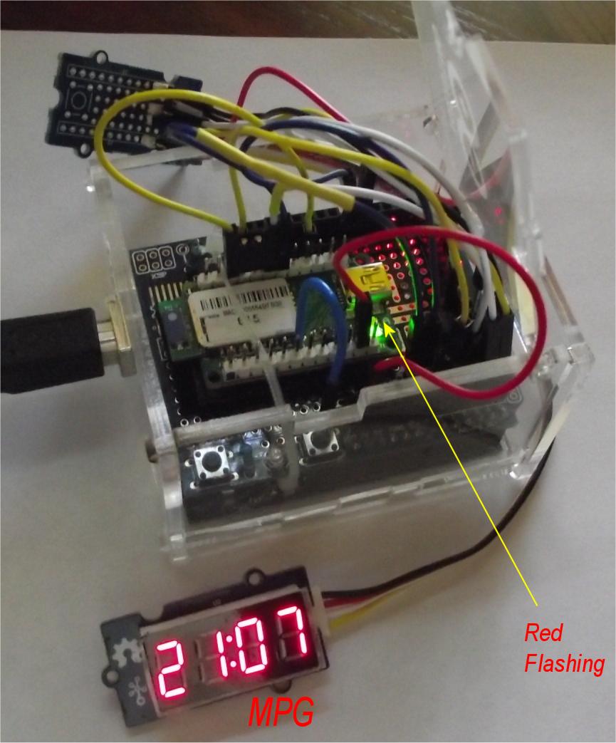
I added and LED yellow lamp, below, for spark coil 1/5 (wasted type). It flashes, to indicate I have spark. The ECU igniter has no difficultly operating a 20 mA LED. (as expected)
1996 Ford OBD2 ECU with 36:1 crank sensor CKP input . See photo below of this tone wheel, the trigger wheel with the obvious NOTCH.
Warning 1, on most cars the ECU will not accept this input if the missing tooth is (misssing?) nor if it happens too often. (on newer cars, the CMP is compared to cam angle if WAY off, (time) the ECU shuts everything down
and barfs out lots of DTC on just this, P03xx errors. This is how all ECU's work. Some are easy to fool others are RAD hard to fool. YMMV.
In fact, getting the CKP working is job one, if I can do that, I'm home free. (on a Suzuki engine ECU say G16b, only the CMP needs to work up to 1998)
This ECU is real fussy, on the CKP input unlike old Suzuki (Suzuki, needs only CMP square wave "HALL"), My FORD ECU unit, must have a CKP drop out, for #1 or it will not fire ! at all..
For fun: (playing around, trying to fool it) (I have a shelf full of signal generators of many types, sqaure wave, sign wave, and function gens with triangular wave, you name it , I have it.)
I tried a white noise Generator , as a CPK signal (for funs and giggles) and could get random firings, ( I'm sure the ECU sees it and goes. its good, no its bad, and repeats)
This told me , hey dude, you are getting close, it wants to fire.... True hacking....
But I already know, that many ECU's the tone wheel has a GAP. and is MANDATORY. (not seen on my Suzuki)
The proper 36th tooth signal , is key and necessary. (360 degrees divide by 36 is 10 degree's , so now we know the CKP resolution , it's just 10 degrees. but the edge of the mark is DEAD nuts accurate)
The CKP device below (a signal generator or function generation (processor based) and later replaced with the Arduino card. ($12 clone and you have a good signal)
All code is below: (it is crude and can be vastly better if you yous timers and not loops, but I'm lazy.... a retired puke...)
Here is my Arduino code. (working perfect now, 800 to 5500 RPM)
PINS?, those silly 1mm pins: ouch. 1mm pins are like Chicken lips here in USA. ( Jimmy Carter is still mad, can I blame him , no) Jimmy was Mr. METRIC. (when POTUS)
The ECU gold round pins , are 1.0 mm diameter. size, & rare in USA, but can be found on aircraft and mil connectors. I found some. took a long time. Too long...
I gave up on finding USA 1mm pin socket terminals, so ordered 35M4160 , these from Farnell/Newark/element14, out of UK. 100 pins for $10 ( Newark14 is still charging huge packing fees.! I avoid mostly)
The best pins were the ones from Newark Element 14 above (shipped from Europe storage) (Newark ,in house, inter warehouse ship method)
I found 1mm pins from AMP(TE) "Tyco" p/n #571-770988-1 (from Mouser) fit, but are a tad loose. (into attic they go)
end PITA.#1 pin's.
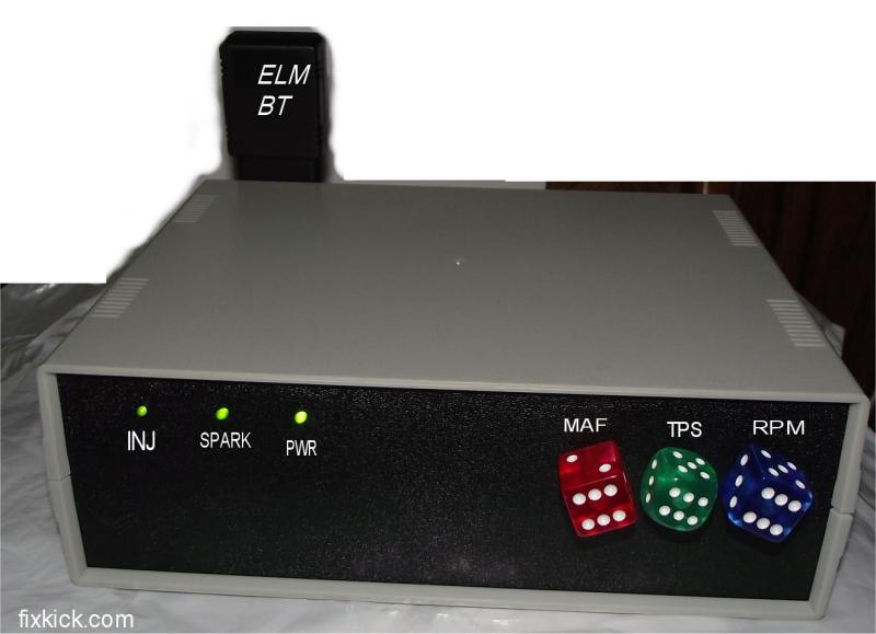
Done: (below) Added Arduino base. Project 1 is done.
The second transformer was needed, due to MPH (VSS) input signal , must cross zero too, or it to is dead, just like CKP dead reasons.
The VSS has a coil of wire in the SPEEDO and a magnet (in car), so says FSM 1996. (not a HALL sensor) 100Hz is 50MPH, on Fords.(so it says)
I can now plug in , any scan tool or other OBD2 devices and do tests , with no engine, car, or vehicle of any kind. (including, my home made MPG gauge)
I get about 40mph at full RPM. (revised code, in Arduino) My project 1 is a done deal.
Knobs are for an electric Guitar amp. , dice knobs. 50cents each.
The wall wart, is 12v @3amp.
The Wifi link by Scantool.net. UNO card is in blue. About $40 total , not counting scan tools. $10 ECU from fleabay.
I have about 5 top scan tools , all work here, if car is 2008 and newer you need a can-bus rated scan tool.
The MAF knob simulator is 5vdc (org wire) and ground (blk) to ends of POT, and the tap takes off 0-5vdc to simulate MAF in ECU, (white wire)
TPS knob is same ,the pot across 5vdc andn ground and striped wires to ECU is TPS voltage 0 to 5vdc.
The RPM knob, this is just an adjustable 0 to 5vdc level that the (A0 pin) Arduino uses to run the CKP pulse rep. rate in the code. see 10k resistor to protect Arduino input.
The power pack runs both UNO and ECU with 12vdc. the org. 5vdc wire steals 5vdc (org) off of the Arduino pin of same name.
The code page, has comments for eachUNO card pin.
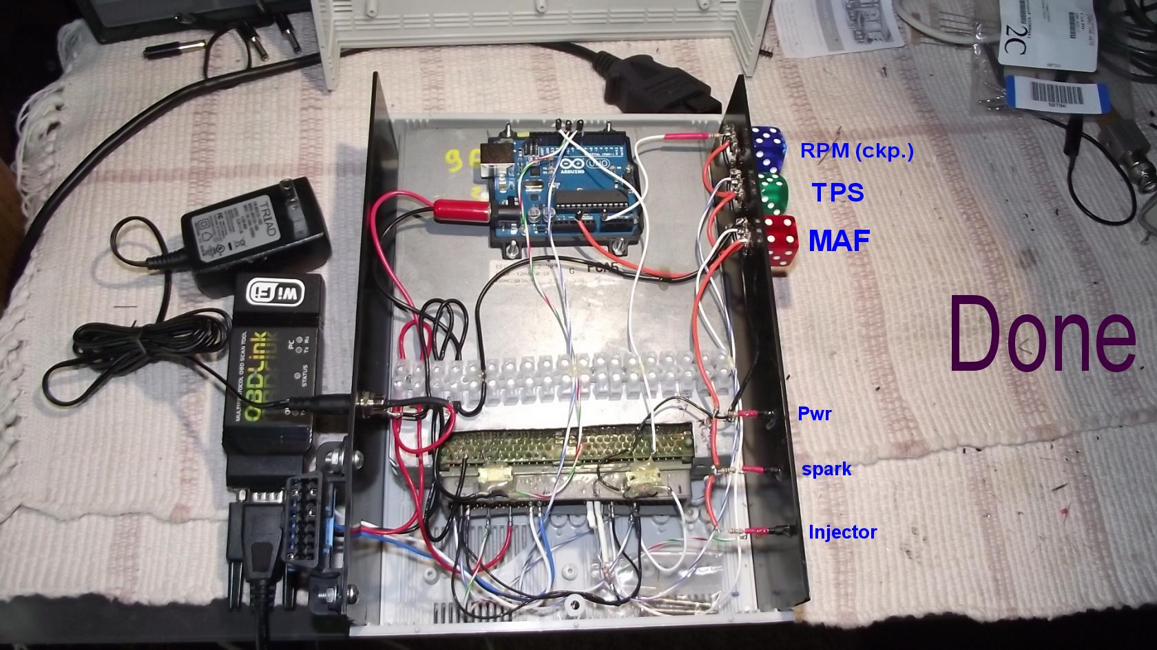
As you can see above the transformers were glued down using HOT glue, that drive CKP and CMP inputs to ECU. The transformer shifts the signals (digital) so they cross over 0v fully. Fooling the ECU 100%
The wave shapes are not critical , only zero cross and timing. (the cycle rate of pulse and its timing are important as is the 36th tooth.)
The input to the transformer is a perfect square wave that staturages the core of the transformer, but the ECU could care less ,it only sees the transistions from zero crossing detectors.
The transform sends a signal that goes above ground potential then minus. Just like the real CKP, does, but looks a bit ugly. (and works) (we learn this in Military Electronics schools)
Xicon #42TL009-RC
This Mouser transformer, for above is $1. The black wire (ground) on right transformer is daisy chained. clearly.
The right tranformer bottom wire is CKP
The right transformer top white wire, is Gen input. to trans. This Audio Transformer, is 500 ohms on both sides, so there really is no primary /secondary, its symmetrical.
The transformer supplies the needed zero crossing detector signal rules on the ECU .
I get injection/spark as soon a power is applied and CKP is happy. (if CMP works too, it gets more happy, less DTC errors) Mine tells my DTC errors for cam timing.. is off , and is....)
Lid back on, lets now fire up the blue tooth and do my first , MPG project. (Miles per Gallon Gauge !)
My Engine simulator is done, no exhaust fumes while debugging.!
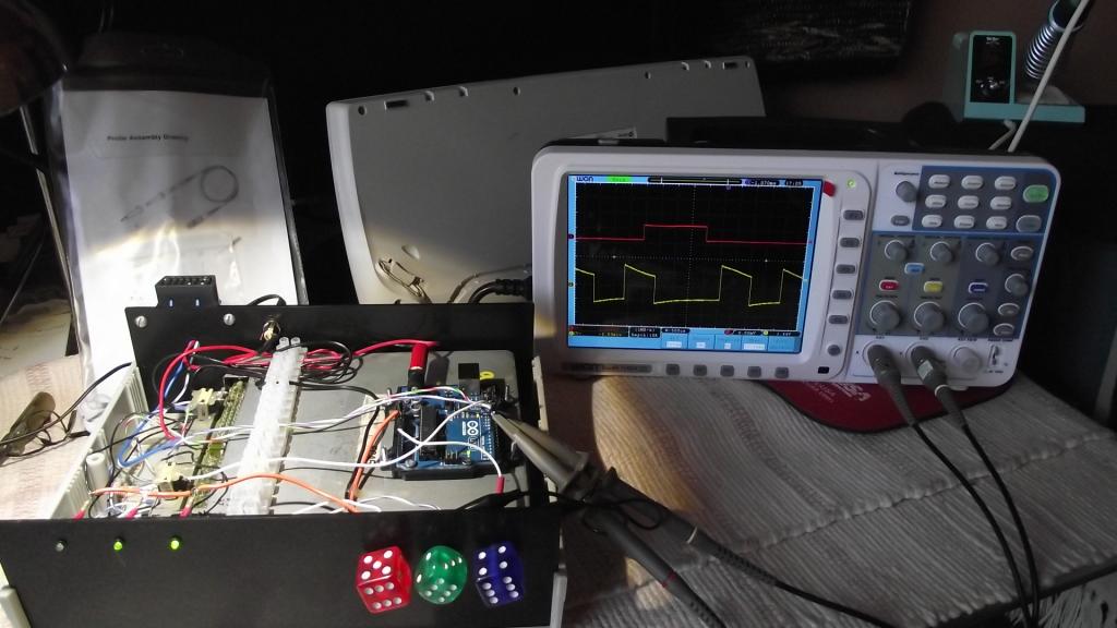
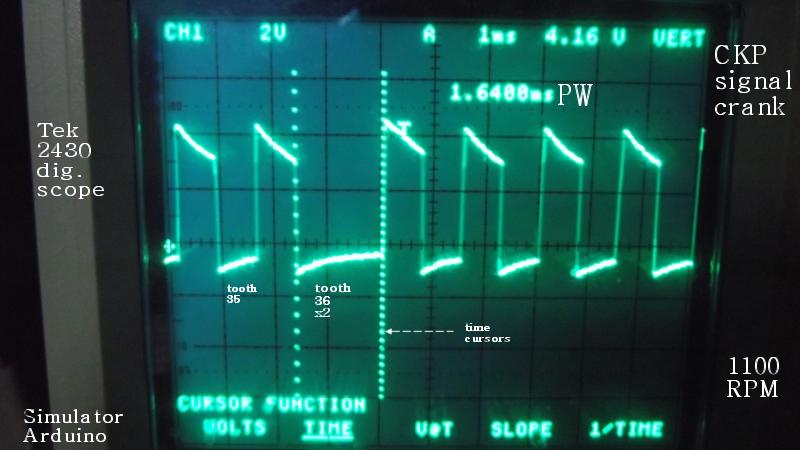
Below see CKP in yellow trace and red is cam sig.
The Crankshaft "CKP" trigger ring looks just like this. See the missing tooth ? At about 2 PM? we must SIMULATE this ring teeth and that missing tooth.
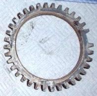 The real Ford CKP tone ring (a reluctor) a 1 of 36 ring. Crank Position sensor RING.
The RPM rises and MPH increases too, in my code (crudely) With this device, I got my MPG arduino code rock solid.
Here is #36 tooth captured in memory of my Tek 2430 , the over shoot is the back EMF (electro-motive-force) from my tiny transformer primary. (aka: inductive kick back, to a tech)
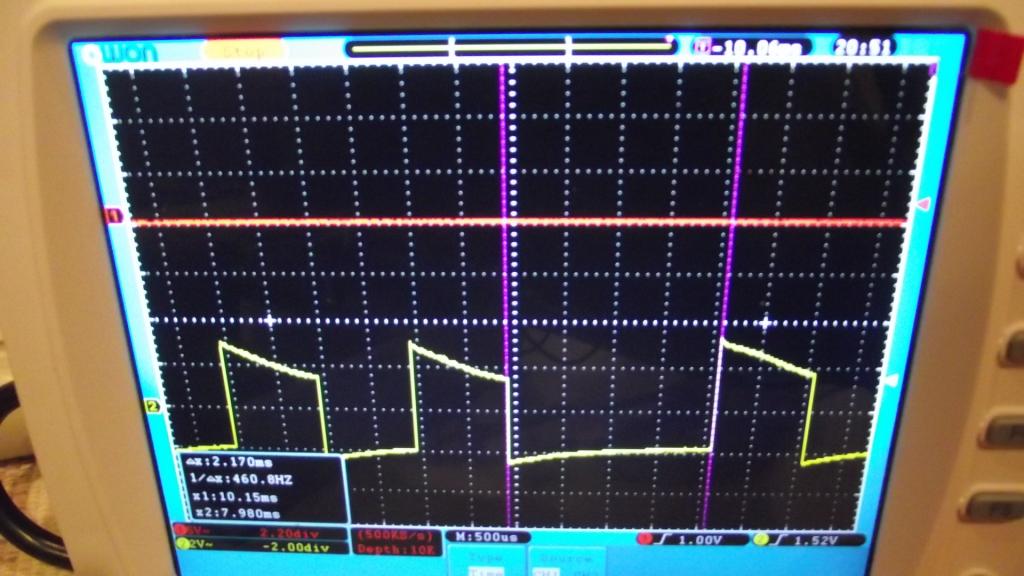
These (both) transformers gets me perfect crossover to the ECU. This one, is the most important.CKP. My goal was to get spark and lots of DTCs, to spit out for testing.
Owon 7102(v) (2014 new scope with sexy find longer pulse trigger feature ! ) That slope is the transformer recovering from Saturation, cool huh? That slope is the mag core field collaping.
BOM: {bill of materials}
- A FORD or any similar ECU, best is one that only uses HALL sensors. (I'll try to find one later, and put that here, A toyota would be nice, and easy to find.)
- A case.
- Some knobs. Any that suits your fancy.
- The Mouser sold Xicom # 42TL009-RC(fixed bad link)
- Potentiometers 1k ohm pots. 1k is best. for MAF , TPS and RPM . if you want ECT and IAT Pot.'s 2 more pots. 10k ohms.
- 1x 10k ohm resistor on the RPM pin. 3 cents.
- The Arduino card .
- 12vdc @ 3amps Triad power pack or from Mouser
- Any scan tool that matches your ECU/PCM OBD2.
- OBD2 port female with pins (16pin) (order pins below photo at Digikey.
- Any power strip that floats your boat.
- LEDs from 1 to 10 ? (injectors, power, spark (ignitor) etc... .
- Resistors 150 ohms for LEDs. to match above.
- wires... gotta have lots of wire.. above is mil spec Teflon.... (near free off ebay)
- ECU needs 1mm female pins, (hens teeth rare ,ask me for some, for free? , I had to order them from European Newark14) (best is to rip ECU harness with ends out of wrecked car....) this was my only hard step, dang...
- $10 ECU and is broken in a way I don't care. 1996 Ford 3Liter v6.
- 1996 is dumb and simple OBD2 ECU. (no Immobilzers, no other hard to simulate parts , just simple analog parts)
- Direct fire wasted spark coils,
no ICM modules to fool, or reverse engineer...yuk. (ICM = ignition
control modules, that nobody makes schematics for or spec. out as seen
on 40 million Corolla's)
- The CKP is coil type, (only hard parts) The CMP on some are HALL, easy to make signals for any HALL sensors. Here is a mp4 of me testing one HALL CMP with LED.
- Starts easy with just CKP signals. and better if CMP works.
- The one trick found was the MAF has power pin5, if you don't connect it to 12v, the MAF is born dead (my pot simulator failed to work first time)
- I didn't like the 1 mm ECU pins, but that was a surprise and not expected.
- I used hard resistors for sensors I didnt care about. IAT, set to 150f (7k ohms) and ECT to 200F.( 2k ohms) fixed. ( you can use pots here to test cold start. for fun)
Once I saw spark and injection wake up, I made my nice box.
I did not make a schematic sorry, because you will be using other ECU's. There are not too many wires, as you can see, and will make spark and inject with just what you see.
What is connnected? Power, ground, OBD2 comm , connector. Simulated MAF, ECT, IAT,TPS.
But ,the Sensors are all running (not CRANK) off 5vdc. I used the Arduino CPU boards 5v OUT to run the pots for ECT, IAT, and TPS see ORG wire? See it daisy chain.
The ECU has a 5vdc OUT pin 30 and I should add an LED off that pin to show the ECU +5vref pin is not dead.(a common failure that)
The black wire is ground. Red is 12vdc from the power pack.
The RPM is connect to the CPU via a 10k resistor, to make my RPM pot. less radial.
I did not use 6 injector LED, or the 3 spark line LEDs , just 1 each.
The ECU pins are different on all different engines and years. (you will need your ECU schematic to figure out the pinout there)
2 pin CMP/CKP are coil types, (tricky)
3 pin are HALL. (easy)
My goal #2 is to connect the fewest possibe wires to get it to work.
This page does not cover, how to simulate sensors that broadcast , PWM data to the ECU, Like some older Fords did with their MAF sensor.
This page in no way , allows or helps you cheat the SMOG man or EPA, in fact it does just the opposite, it fails EVERYTHING, and is/was my goal.
END FORD OBD2 SIM., It is a DONE DEAL ! (my only goal, was to make the most posssible DTC errors, on the bench.) To test sensors and scan tools and scan meters.
Any questions, ask me... please...

What else can I do with an Arduino UNO card (MCU micro-controller-unit ;brain)?
Project 2: The Analog voltage Data logger: Have FUN !
Well, you sure can make a cheap, stand alone , voltage logger. (Many folks have a smart DMM , with USB and can do this at any time, but if you do not? and want to make one , here you go)
( A very powerful tool, and a huge blessing to finding horrible intermittent failures in cars, vehicles of any kind, when lacking DSO (like the Tek TBS1000 USB logging scope?) $520
I'm making one, with my 2nd Arduino UNO, and this standard logger shield from MCM , using any Arduino A/D input
This log device, you can measure voltage, at a great rate of speed and log the voltage and time stamp, each logged value, to the SD memory card. (a total cost of about $50, surely 10% of my scope)
All the software is free, and your "C" code is free too, Pound away ! at the keys.
You can write (called, oddly "Sketches") some simple "C:" code and make a simple program loop.
I will give you "pseudo program code" below (and real code later) {aka: programming instructions, you get to pick what you want and what features to use.}
- Define A/D pin x. (the pin under analog test , you used)
- open log (SD card)
- loop (these creates an endless loop)
- Read A/D pin (analog)
- If ? x not true, jump to
end1 (x <= 11 v) (x is the voltage
measured) This if instuction finds a Voltage drop out , in the
Vehicle. If not fail, do not log.
- //
log only failures (or if you want , log everything, it is your choice,
in fact add push buttons or switches here, to make it do what ever you
want. (eg: log fail , log all, , log off, etc )
- write analog to SD, (with time stamps, RTC chips) RTC means Real Time Clock chip ,on my shield.
- End1:
- keep looping. this loop runs endlessly. The processor , just follows
your instructions 1 by 1. (the only event driven features, are
interrupts, not used here)
Say you are expecting a drop in 12vdc power. You can detect it and the log the whole event.
You can connect this device, to a point all over the vehicles , harness and find HORRID intermittent. ( I found a bad factory splice in a Toyota dash harness, once, had to remove the whole dash , dang !)
If you want to get fancy? , say testing any 12v line in the car (or ? ANALOG lines in car) that are intermittent (you make a connection) then put one , "IF" instruction ( IF volts > 11v , jump to end1 {skips logging})
This freezes (spins) the loop until the measured line fails. (this is what I call a TRAP) if the voltage sags below, 11volts , you get a full log , of the whole event in the SD memory.
Sidenote:
I also have one, small Tbox (testbox) with some simple electronics (a TTL FlipFlop- latch), that does the same thing, if 12v drops, it trips, and glows and LED. (it can only capture 1 event, unlike the above fancy logger gadget)
This old Tbox is just a 74LS123 one shot inside, set up, as a falling edge detecting, latch.
My below data logger , I could add 1 more LED and one push button, that starts the loop when you press the button, and when the voltage fails, the LED glows.(for feed back to said human)
The enhancements are near endless, but here are a few:
An added display with status of the loop, last measured voltage, failure count (12v failed), and a freeze feature, that turns the display in to a voltmeter. (and IF instruction the ends logging)'
More later... They sell these professional tools for $800. No need to do that. Make one.
If you make a V. logger, you can make it do, what ever you want, or even tune it so it finds (discover ) some unique failure in your system. (over shoots, undershoots)
To be added, a push button that starts the SD CARD logging.
The serial data will always log to the USB port. You could also log, using a lap top PC, via the USB port. (running the stock Arduino IDE and the "monitor" button)
I got it all working, in about 1hour. I used a 9v battery , pack (6 x AA bat) to remotely log data.
I just followed, Adafruits, page on their logger shield and it works perfectly. I have a micro SDHC 16GB & adapter in the slot and it work great.
Here is my working logger code.
Here is my logger hardware , seen in photo , above.
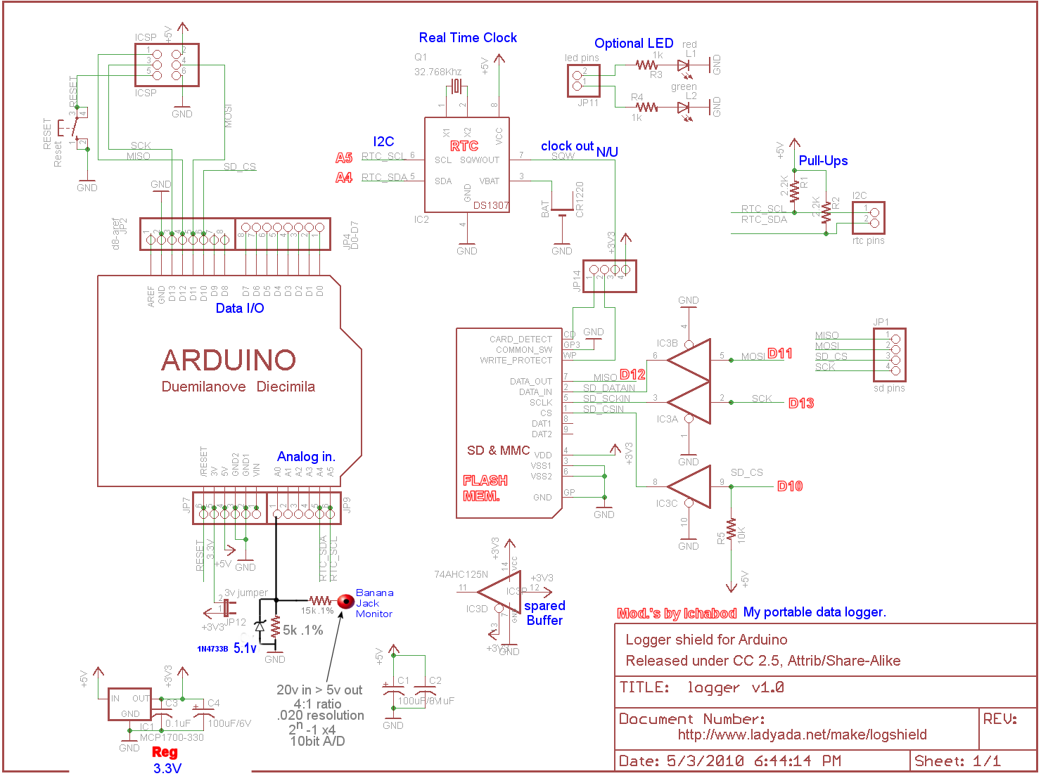
I made one more change above, allowing me to measure 12v or even 15vdc as is the common running voltage in cars. I added, a Zener diode to protect the uP. Max input on the uP is 7vdc.
Sorry for slang, uP means "u" for micro and "P" for processor, as in micro-processor , uP for short.
The zener must be 5.1vdc, . 1N4733B A Better clamp is a Shockley Diode, at A0, (anode) with Cathode +5v Arduino pin above. I use 'ON Semi MBR160G"diodes, (bags full in my parts bin) Mouser has them.
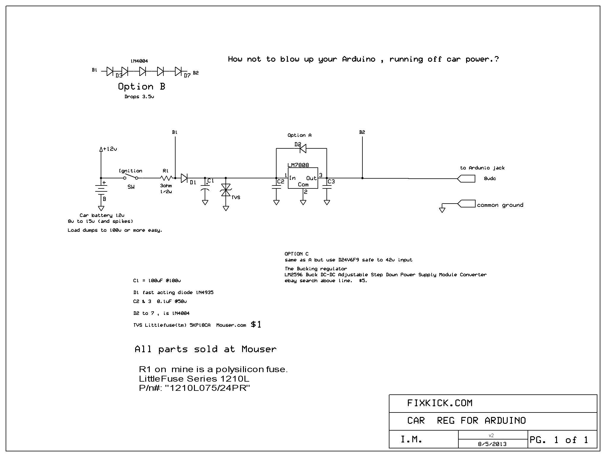
Keep in mind , that I am inputting (CAR) POWER voltages from 0 to 20vdc and NOISE Spikes, load dump spikes or HVAC, A/C clutch spikes ! 100v spikes, are easy to get there.
A TVS diode clamp is advised. (I use them, in all my power supplies, used in cars) 1 example.
What can I do with the above, logger? Keep in mind it can take readings , in aboput 260uS or 3850 times per second or faster. F = 1/T
- Find intermittent power wires on a car, I connect,
log and catch (trap) the event, move my test point and isolate the
EXACT fail point.
- Monitor the output of the TPS, and see if it works or as many are intermittent. Log it and watch it, saving $100-$150 on new TPS parts guessing that it is bad, and is not.
- Monitor
ECT, IAT, or MAF. To see if they work correctly, driving, and if
intermittent or not. (An OBD2 scan tool works better here)
- You could add a Active temperature probe to the Jack above and monitor coolant temperatures (any where on the car; you want)
- With a current probe, even monitor current flows.
- Let your imagination work here, you can add a local display, thus creating a volt meter or ?
Every battery has a different amp/hour rating and its own chart, that shows load against time. yes, all batteries have data sheets.
end logger
PROJECT MPG GAUGE! Using my new Virtual Engine, constructed above.
Goal 1: It must run on all cars 96 to present. Even Ford ECU's like seen above.
Goal 2: Not blow up the chips, I see many (vast) web sites, just throw together parts, then wonder why it dies a week later, or 1 day.
The Arduino is 5v the target chip is 3v, believe it. Don't use rumor, to decide, read the datasheet.
My biggest peeve is the horrid documentation, the biggest problem , over all with that, was they never even explained the STATE MACHINE. ! Amazing !
Slang: BT = Bluetooth, and BC is , BlueCore.
I tried, 3 different brands of CHIPS.
First off, a big High Five to CSR Cambridge Silicon Radio Limited, to a company that make chip BlueCore4 ®, there is ALSO, a new, chip by STmicro.
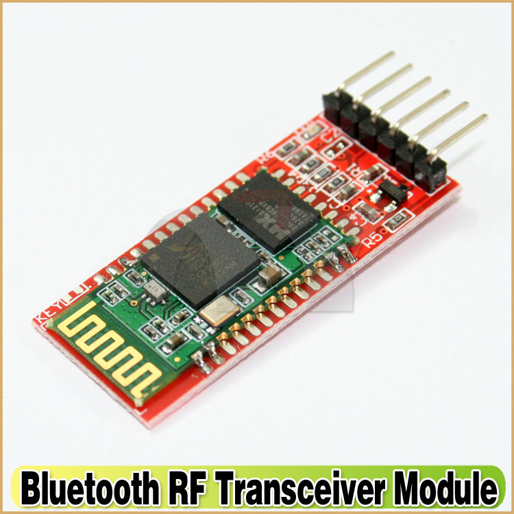
This one chip BC, is used in each Bluetooth module shown below. (in many forms)
The CSR chips used , are a value added product, and I tried, them all below, HC05, SEEED 3030, & Roving Networks® RN41. ( 3 protocols used)
No lie, the RN chip is the smartest and most useful.
The future? The below, is a brand new product: I see Panasonic just added a new BT product listed on Mouser.com.... Lots of choices, now.
Sidetracked:
If bored?, lay out your own base board, for this classy , chip, STmicro SPBT2632, it's 5v tolerant too . (keep in mind the best 5v Tolerant chips are only 5v safe, on some pins)
Based on ST-Ericsson chips, radio STLC2500 and STLC2690
The STmicro have fantastic documentation see the models here.
STmicro, gets top awards, for explaining the inane Apple rule's for getting Apple products up, a secret code chip and an annual license fee, to name 2 pains in the ash can..
This new product, is cheap , as cheap as $17 or less, this product will drive the RN products prices down. Nice.... As will Panasonic's, 2013 release)
I have not tried the STmicro, yet.......
back to my 3 devices , below.... back on topic, Bluetooth and MPG.
I'm building a real GAUGE , not playing with some cell phone plastered to the dash.. A permanent dash gauge, with a " OBD2 Closed LOOP" display symbol and MPG live. (instant ,or updates ever 3 seconds)
My gauge cheap, not a $300 Smart CELL. No body will break in to my car and steal , my 7 Segment LED.
The Bluetooth "BT" is the best choice for wire free operation, like me, my cars DLC is in a bad spot, and having wires there, are seriously problematic, and I am not moving the DLC. "Data Link Connector"
Project 3: MPG
Before jumping off this cliff, read this page first on the product.
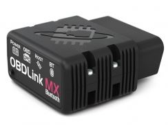
My block Diagram of the hardware. The best BT OBD2 scanner module is this.
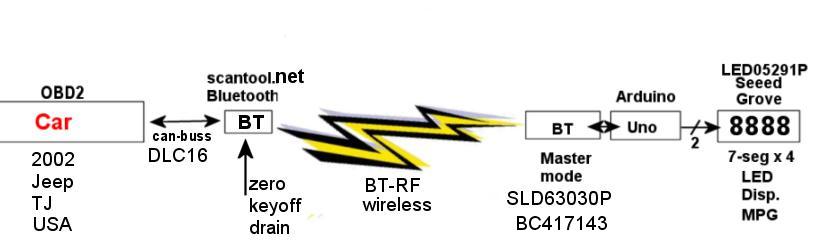
My scanner is and ELM 327, The STN1110 is vastly better.
To get mine 100% fault free, I had to count response characters, and sniff out, ? , "No Data, Stopped, and Searching.., messages", (I reverse engineered that, and got that to work. ).
The 4 errors are in the ELM book, what I found out, is how they come in to play and more importantly , for HOW LONG the events take ...many seconds..
I tried each of the below, and each worked ok. I had to learn the protocol of each. The bluetooth part was the most easy. (after training it... sigh and poor documents...)
A quick REVIEW:
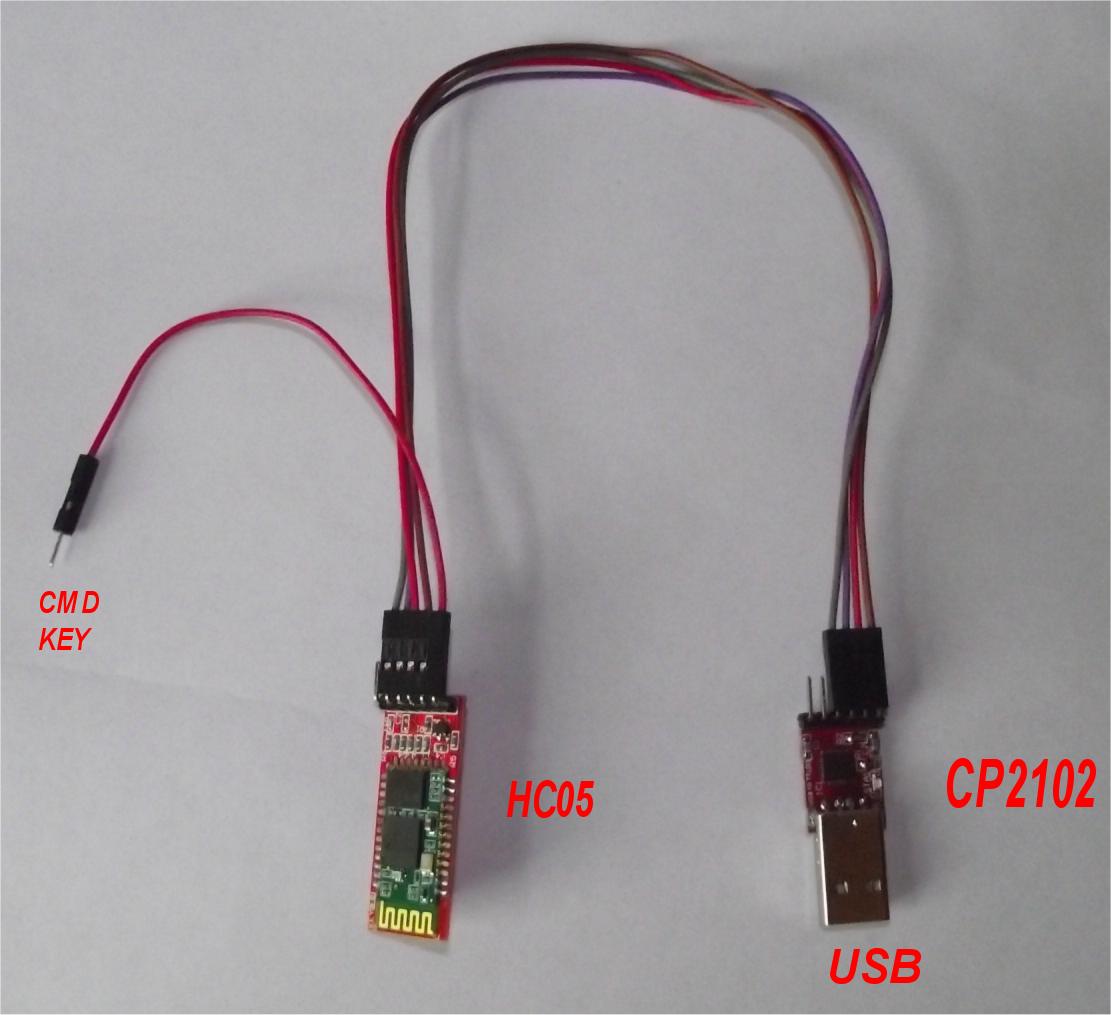
Runs on all cars 96 and newer. (USA Cars !) The white wire, on the HC card above is my added reset pin mod. (later found out it's not needed. at all, again bad documentation)
The HC05 KEY line chip p34 , when raised to 3v, latches in, Command mode.
I just jumper this pin for 1 second and it holds command mode forever (until reset). (with no BT slaves connected, )
This is why I complain about the poor documents and the lack of state machine rules in their Docs.
- Power up the HC chip.
- No slaves connected and if true, command mode is dead. (can't get there..) (turn them all off) My slaves autoconnect in about 1second, so turn them all off.
- Bump pin 34 high (TTL VOH) use a wire, a momentary switch , or what ever. just pulse it high for over say ,1 uS.
- This act latches in Command mode, and is not in the
book. and 99% of the web sites for this chip tell you , to
cycle power, and is totally unncecessary.
- Using the power dead, Pin34 high, then power up way, works
but is the all else fails brute force way. This has value, but is
mostly not needed. (say, you scrambled the HCs brain)
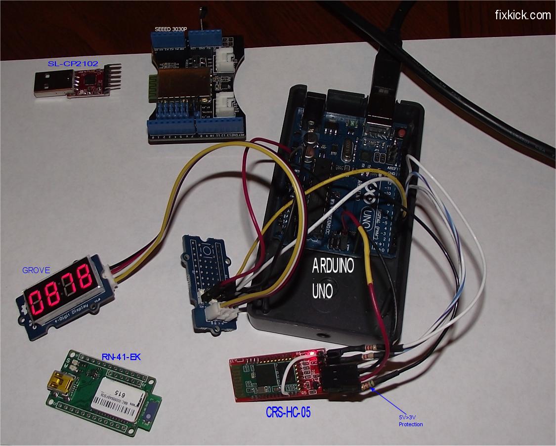
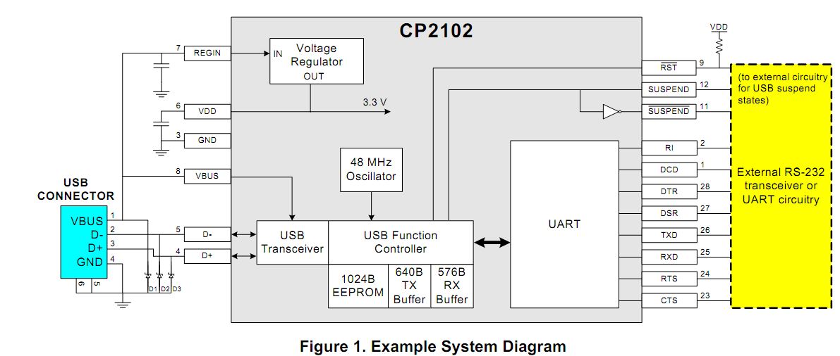
The best way to get these HC05 parts working is to connect the CP2102 (USB>TTL-UART) to the CSR(tm) HC05 and learn its habits.
A FLOW:
- Program the HC (configure it)
- Cycle power
- Get it communicating with the slave. (and does so , each power cycle)
- Then use the BT device, as a Virtual TTL serial wire set, use it like it is a magic connnection.
Practice at the communications. (what I did?)
Best Path to success:
- Get it talking using the CP2102 (with a RN-41-EK, it come with CP2102 on board)
- Learn how it works.
- Program the device using CP2102
- Get it connected to your slave (this web page is master mode only !)
- Reset the power to the device. (locking in the above.
and enabling above, in fact you may have to cycle power for every
technique used above, for the effect to be seen !!!)
- Does it reconnect automatically. now? If not repeat above, until it does.
- Then run my program code (sketch) below, my Arduino program, "C" code. it does work.
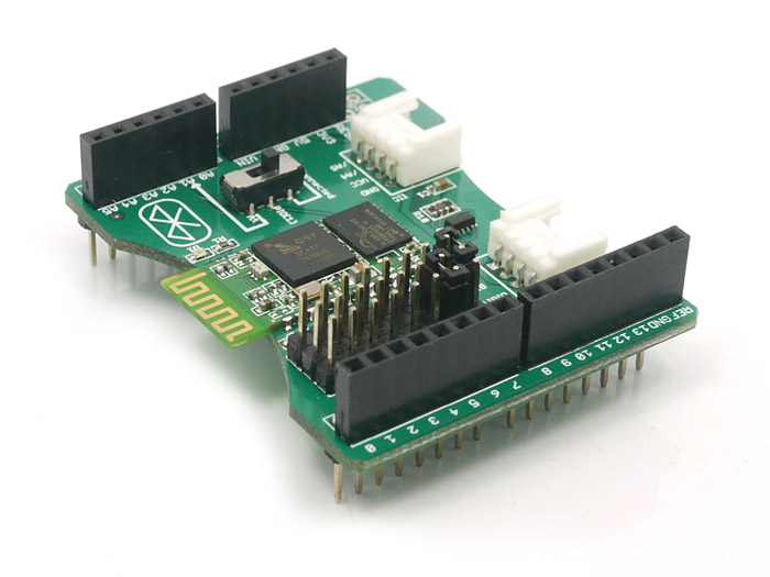
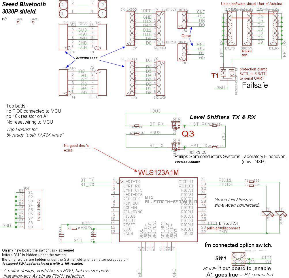
I tried this 3030P Shield. (by Seeed)
The SEEED was the most hard to get working, due to horrible documentation. (you get a short list of 15 instructions, but do show connecting a SEEED to a SEEED, well)
Here is my working SEEED code, 100% up.
For a $10 Arduino and $20 Shield and my code, you are now up. with MPG and closed loop. My revised SEEED schematic, is here.
I think all 3 devices have the same CRS BlueCore4®, BC417~ chip hardware, but each brand device ,has different firmware.
You are buying firmware, and smarts. (versatility); Smart is never free. Each maker adds their own STACK command set. In fact, this ability is the brilliance of this design.
There are 3 protocols:
-
The $$$ version
(RN-41) (BC417 based) (60sec. window for $$$ to work at
power up) $$$ is a software command mode enable, once set , it
holds.
- "AT" version (HC05)
(unknown firmware but chip is BC417) needs a hardware 3v high to
enable Command mode. This mode latches in. At anytime not BT connected.
- "\r\n-command-\r\n version" (SEED) unknown firmware, and the worst documentation. It is BC417 based but has only a list of 15 commands, for documents. very very poor.
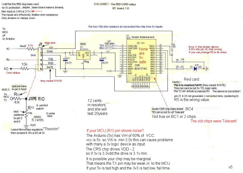
I bought the below red card, that uses the "AT" command mode
HC05: This chip is popular, just because it's $5. (billions sold ! into many applications.)
There are many HC05 cards, most have no 5v PIO tolerance at all. (only the more expensive and rare RS232 board offers 5v safe RX /TX pins)
Here the very common 6 pin card, here is my fully revised drawing.
The chip used is the CSR Bluecore4, the data sheet is here. BC417~ based. BC means Bluecore.
Data sheet, (hard to find but here it is) see max levels.
The CSR BC417143 chip (all 3 tested here, do) and a huge Flash memory. . see the top side naked here.
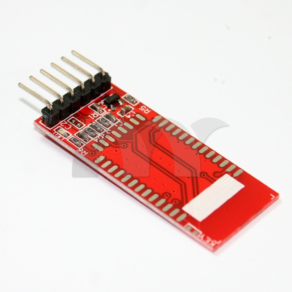
The below RED based base cards has RX and TX labeled WRONG in reverse. (red cards only) way to go ! huh?
ALL 6 pin cards, with no base board protection are not 5volt input safe at all, for sure not RX. The max is 3.7v (3.3vdd +.4v) { if VDD is lower, so is max input!)
Here are 2 solutions, to this issue:
The HC05, products, lack the following facts, in their documents:
How to get to Command mode, short and sweet. The big secret?
- Power up. (no slaves about, if you get an auto connect now, all the below fails) A Tricky beast, No?
- Raise pin 34 CMD pin to 3v (command mode) via MCU (do not raise it to 5v, ok?)
- Lower pin34 , and Command mode, is latched in. Try AT+STATE? cr/lf. ("\r\n", in C code)
- Issue what ever commands you want ,say ,change the PINCODE to 0000 ? or ?
- Issue "AT+RESET \r\n". (this ends command mode now latched up) I proved all this with my CP2102 USB comm.' device.
- Bang you are in passthrough mode. (aka, communications mode) Pretend BT is a pair of TTL232 serial wires. now...
Warning , if you use power or RESETB pin to enable, command mode, the baud rate can change, RTM! Best practice, is to not do that.
 scantool.net net real.
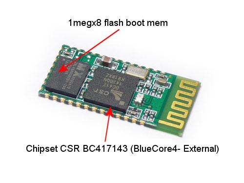
The below is the red card schematic (not the RS232 version): A good name for this card would be HC-05-3vTTL
I added a 5.1k resistor to J1 pin 1, (5v protection) and 10k to J1pin6 for my connection bit monitoring. The 10k protects the BC05 from your Arduino, if it ever messes up and grounds this pin.
If you want and LED on STATE, use a 330 to pin STATE J1pin6. (you don't need an extra LED as the D2 flashes an unique code on connections.)
If you want both, install the 300 ohm and LED then add a 10k resistor to pin 6 and monitor that way.
As you can see, the board runs on 5v power. (via U2 regulator) but the card is not 5v safe. (not at all). NOR are the PIO pins GROUND OUT SAFE (RTM).
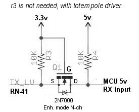
The guy that thought up R3 and R4 must have been sleepy that day?. R3 need to be 6K not 1k, for 5v TTL usage. The best R3/R4 is 8k/16K, as the chip maker states. Thevinin equiv, tuned.
The R7 is missing (it's a short), oops. Don't wire any LED direct to this pin. the board has silk screen errors , and is not 5v safe as advertised. TX and RX are backwards. ho hum. Water off ducks back.... Quack!
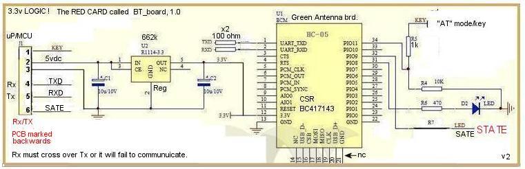 note pin 21/22 missing grounds,(bad)
MY HC05 code is here:
My code is posted now. (here ,called "hc05.ino" )
end HC05; experiment. Mine works 100% perfect now.
Roving Networks RN-41 series Bluetooth master, usage RULES: This product is a Class act ! (I still working on this project)
The RN-41 (Roving Networks ®, (with Microchip® and is a CSR BlueCore4® is the best. Roving extends the command sets, to the stock CSR chip STACK !
UNO (Arduino) meets RN-41. (with breakout shield and some Velcro, to arrest the RN,and 1 tie wrap)
Nobody sells large Arduion boxes, (taller) I had to find a plastic box, that is radio signal friendly, ABS 2.5w x 4L x 2 H" minimum.
Finding boxes is not easy. The tall/ height on many are too short. Many give the outside measurements and not the inside, which in injected plastic, is far smaller.
I needed room to fit my shield and my wires, and my bucking power supply. Bud box BT-2723 clear blue plastic
It needs room for my 12v to 8v bucking regulator for car power.+ my mods there. (I built a car noise test generator long ago and made this, to survive any load dump event !)
The Blue wire below, is a super size ground; Those China made thin jumpers, don't work for ground at all. (use a scope and see that)
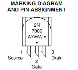
The Generic shield below holds my 2N7000 and my diode clamp.
This setup connects in 1second now, every time I apply power, 30 times in a row , tested now.
I have DIP sw3 enabled for auto connect, if using the cheaper RN41 with no such switch, connect a 10k ohm resistor from PIO6 pin to 3v (high) this causes master auto connect mode #3 to happen.
The box below, is now gone it was only for testing. See the final box is below, The Bud BT-2723 , I will finish up with this box and run my display to my Dash.
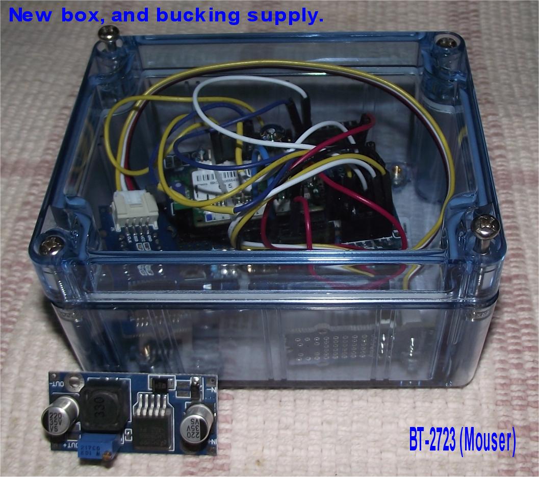
The little blue module on the right photo above is the bucking supply, 10- 40vdc in and 9v out. The car can have wide inputs ranges, including spikes, I have protection for that too. The RF, needs PLASTIC to propagate.
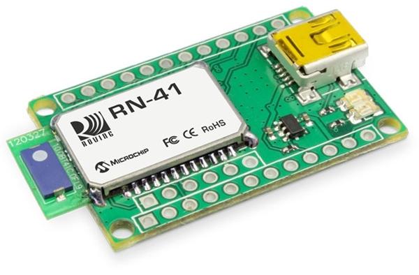
Under that white label above is a (again) Bluecore chip (BC417?) and with custom RN programming (features and protocol); Class 1 device too. 100meter range with both devices master and slave Class1.
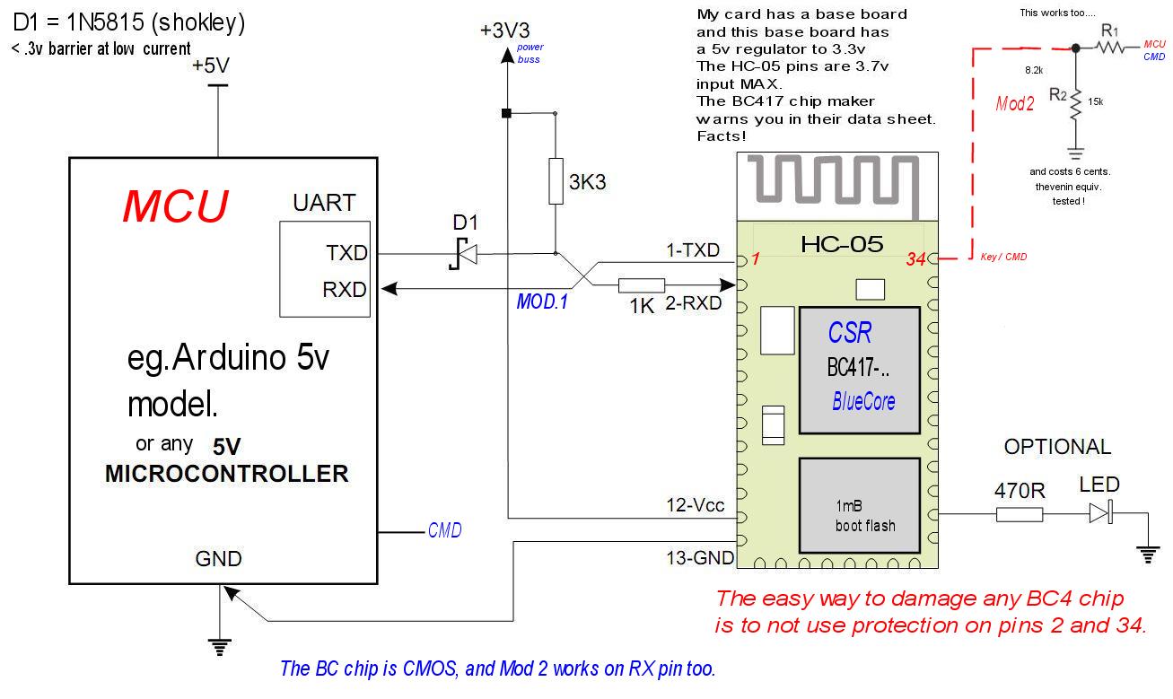
I'm marrying a 5v device to a 3volt device here. Using proper, level gates and protections.
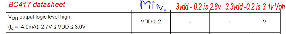
The RN-41 puts out 3v VOH, and the Arduino Atmel needs, 3.0v minimum. In many cases it works, but not all, and is marginal. So If yours don't work , now you know why.
The Atmel processor needs this 3.0 VIH
The FIX is easy. just like all 3v to 5v interfacing issues. The below is a level gate.
I then added this circuit, between RN transmitter TX (weak) and in to UNO receiver RX. Bang , I now have perfect 5 TTL inputs to my UNO. !
Theory:
Q1 turns on when the RN is low, this gates the LOW to the UNO MCU. when RN41 goes to 3v logic state the Q1 turns off and the drain floats, and floats to 5v via, R4.
I don't need R3 at all. The 2N7000 (28cents) is very easy to find discrete part, and easy to solder, by humans. (unlike many SMD parts, sorry no SMD labs here...) SMD=tiny Surface mounted devices.
For sure the below is the best way to go. Ideally 2 of these , RX, TX. I use a 10k ohm resistor on my CMD pin, so that when booting my Arduino, it never grounds pin 34 ever as she boots(a very bad thing)
[ side note: if you load and run the wrong sketch (code) into the arduino , or grab one loaded already with the wrong program and it sets 0v to the PIO pins, you may blow up the RN41, so easy to do that....]
Never allow your MCU to directly ground any PIO pins under any connections, (and shorts to power either, I need not say)
The BC417 datasheet. Under the white sticker and SST Faraday shield, lays a CSR chip.
The Atmel data sheet states on page 313 , VIL = 30% of VCC. VIH is 60% of VCC or 3.0v. so I must drive lows below 1.5v and above 3.0v, at 5v. clear as day. see foot note 1 in the data sheet,
A cheap $2 fix is here. LV to HV conversion, and BTW never use and inverter buffer of any kind, but 2 cascade is no inversion so works. The Herman circuit is and
The Power supply 3.3v on the UNO can be as low as 3.17v , this must be used for all calculation on VOH out of RN-41.
As the Chip makers says, pretend you have the wrong Code loaded in the Arduino , you connect up the BC417 and you blow up the PIO(x) pins as the BC boots. oops. use resistors. of 10k ohms.
The BC417 is a MCU too. (inside)
Recap: I have RX on the RN41 protected with a Shockley diode and the TX in to the RX of the Arduino level shifted by the above circuit. and my setup runs 100% solid.
MY RN-41 CODE IS NOW here. (see the "IsECUbusy" routines)
Pitfalls: (don't' read this , unless you are in bad trouble with the ELM or at wits end.) It really is, a TOY.
The biggest pit fall, is the ELM translator, and ECU. both can get confused or busy for many seconds. ( I solved that , see my code ,under RN41)
The total lack of hardware hand shake, called CTS/RTS. (Sadly 1), The RN-41, does have HW hand shake and works so good it can run a old dialup modem. Sure can.!
The chip ELM327 pin 15 RTS (busy) is not wired for the Bluetooth usage. See page 51 in the link here.
When I say ELM from now on, I mean the ELM#327. there are for sure better ELMs! I'm using the old crappy ELM. (and old funky ECU, on PURPOSE) My test bed is a double worst case, by design.
But the ELM bluetooth, uses the most crude chips ($Cheap$) to do the interface.
The ELM can not be used blindly, (it has no Xon/Xoff hand shake protocol ,hex 13/11) either. (sadly 2).
I had to create virutal handshaking, that is, I parsed all ELM responses and set traps to find out ,where it is AT and what it is doing NOW! This works great !
I made a conscious effort to get the ECU/ELM to mess up and made my code react correctly.
The ELM is just a toy anyway, read the data sheet , it tells you that, it was created for just experimentation. model 327. The data sheet says, for "HOBBYISTS".
The ELM can go to searching mode with the ECU for many seconds.
There are many OBD2 cars, the ELM fails to communicate with but should. ELM web site lists them all, and why and the solution (the stn1110 new chip)
To communicate to it ,you must look or the following responses and react accordingly.
The ELM can not stack commands, 1 at a time. only one command is allowed, per prompt.
The ELM input buffer (RX) is about 16 bytes Deep, or 1 command. (that 16 includes, CR/LF too) so it 14) The ELM ignores white space.
The ELM has a 256 byte (char) TX buffer, and if you do not read all responses, and let them stackup, then start looking, it will flood out all up to 256 chars. (pg 51)
Our Arduino grabs all TX data into it's own stream buffer. So you will not miss any, but you must look and retrieve them all, every time, or they will STACK up.
There are exceptions to the above, if using a CAN buss, and direct CAN buss Comm.'s. (very unique and very robust it is) This is not "CAN "buss here.
If you read all the ELM documents ,they tell you about serious bugs in the original design, and was corrected, but most the illegal counterfeited, chips copy this bad code... oops..! It's a counterfeit, not a clone.
My ELM lacks the new, Fast command. Eg. 0110, slow, Eg: 01101, the extra 1 at end, means fast fetch. This also fails on most counterfeits.
- > , means it's ready (this is the most important clue for ready as is the RTS (busy) pin, if you use it.) (pg.6)
- Ready > does not mean last command was good, it just a dumb PROMPT. Most errors end in >
- No Data,
means, PID not supported by ECU. (or your PID is off the wall wrong)
Eg. scanning an old ECU for PID 9 prefixes will all fail. Or scanning a
pre 2002 car for VIN !
- SEARCHING... , this means, in my case, the MAF PID command is busy now , please wait for the answer soon, 2 seconds it takes the 1st time, on mine, and is faster after.
- STOPPED,
giving any command, during the Search, gives you STOPPED , and
stopped means the Search was aborted, a double bad. Wait 3
seconds then try.
- ? means the last command was garbled "syntax error" or just plain wrong. (or too short, or too long, or had NULLs or other illegal characters)
- The ELM can be programmed into TOTAL Death, and only splitting the ELM case and shorting its CHIP pins, can bring it back to life. (page 57/58 in ELM PDF, see links at bottom of page.)
- Buffer full, Buss busy. are 2 more returned errors.
- Some ELM units are missing resistor R36 (ELM counterfeits
,infamous for this blunder, and more...) and as a result some VPW/PWM
applications can get buss errors. (pg55)
Do not send a command to the ELM blindly , ever. (except the first) See my loops and how I repeat commands. BTW, my ECU always goes to searching mode, on first request.
Parse the responses carefully.
In fact, if your software gets lost, then send a AT (cr) command and see that you get a ">" , in response. As a last resort, and this too , is in the ELM manual.
If designing your own custom BT (bluetooth) device, use the RN41 and connect up the RTS pin for busy logic. you will be rewarded greatly, with vastly more simple software.
The ELM chip does have RTS pin (15) but it seems nobody uses it, which is sad because it makes your code far more easy to create and test.
The ELM chip does set RTS false to say it or the ECU is busy, this does work.
The best design would be.?
ELM STN1110 > RN41 ****** RN41 > Arduino. A Pro Grade wireless OBD2 tool. (can be made for $78 qty 1,) slightly more for other OBD2 line transceivers. (you only need one ,if for just your car)
I'm using an 8v bucking regulator for my car to run it all (cost me $2.50)
Logic rules: (just a few)
To be sure ,the 5volt TTL world is Arcane , most chip makers are forgetting it ever existed. Can't blame them really.. time marches on.
Yes, Arduino is arcane. It's for hobbyist, it's not a commercial product.
Rule 1: The CSR BC417~ chip is NOT 5v TOLERANT ever, on its I/O pins. For example here is a module by STmicro SPBT2632, that is 5v Tolerant.
The 5volt TTL Arduino MCU (not the DUE product) will have grave difficulties with added 3 volt logic (3v3).
Some chips, not many , are 5volt tolerant. The BlueCore 4 chip is circa 2004 chip. It seems to me that CSR is dropping 5v tolerant pins, in newer chips. (trends)
This era was a transition era 2001, 5v to 3v, that era is now past ,it seems to me. (cept a few 5v hobbyists)
I found that Bluecore1 and 2 , chips (circa 2001) have 5v Tolerant pins on RX and 3 SPI pins, (only 3 pins, stated in the data sheet clearly) but not BC4( a circa 2004 chip)
Unlike the early Bluecore1 and 2 chips that have 5v safe pins the Bluecore4 (BC417143b) has only USB 5v pins, and does not even mention the word "Tolerant", at all, and does state it's limit as VDD+.4 or about 3.7v.
This one fact is why , people get confused. The data sheet is clear on BC4 chips, read it. Its easy to get confused with 13 years of chip evolution, don't , read the proper data sheet.
Check your base board carefully for added protection, if not found, add yours.
Some sellers of BC4 based devices claim, 5v tolerant but if the protection in not on their base board, then they are fibbers.
By the way: (in real electronics there are rules, this is not Plug and Play magic)
The Arduino MCU floats it's pins, as it boots, that part is safe, but if you have the wrong code loaded (so very easy to do on any ARDUINO) you will blow the BC4 chip wired to those PIO pins..
Rule 2,
Do not allow ground or put 0 volts to be connected directly to any PIOn pin, as you boot. (power up) or at any other time!
Do not put raw power 3v or gawd forbid 5v directly to any PIO pin. on the BC4 based modules.
Or the chip blows up or suffers life shortening damage. (if you do this and push enough current the chip LATCHES UP, and shorts VDD to ground) CMOS chips can do that easy.
CMOS latch up can be destructive or not. How lucky do you feel , today? 3 cent resistors, can solve that, easy.
Do use a 10k resistors for PIO pins set as inputs to MCU, (BC4 card to your MCU)
Do use 330 ohm resistors for LEDs attached to any PIO pin used as and Output, PIO means programmable Input/output.
This rule applies, booting and running at any time. and just before turning on the POWER, to running.
My Seeed card, is one partial exception, and is only excepted on the TX and RX pins. some base boards do have protection , but is very limited to just 2 pins.
Read the base board schematics for the truth. If the pins are naked of any protective devices, it's, well, naked, ripe to blow up.
Commentary on BT modules (the good the bad and the ugly);
No lie, it is a very complex state machine and fancy spread spectrum RF transceiver. (close to magic like).
No fib, the documents stink, the Command lists are great but application guides are totally lacking, pathetic (or totally missing !);
This is Bluetooth device ,etc are, NOT plug and play. You need to connect it correctly and use the correct levels and timings.
There is 1 exception, if connecting two identical RN-41 devices, there is a switch setting on it, that allows instant connect end to end. It does work. Master <> Slave.
Auto Discovery/Pairing switch segment 2 (RN)
I am only connecting to a ELM327 Blue tooth (slave).
One more point, it is best in many cases to program the module separately, that is , using a dumb terminal emulator (RealTerm.exe) and set up the device by hand.
Or optionally write a separate program in the MCU (Ardunio or PIC?) that programs your modules. A 1 time event.
You then power up the module and it finds your slave, in about 1 second. ( I have this working on HC05 and RN41 and SEEED, at the moment)
The connected modules can not be programmed, you must force a disconnect. (I turn off my slave).
The RN41 can only be programmed, for 60 seconds from power up time, and never connected. But can be held in Command mode, after typing $$$ , for as long as you wish.
I fully recommend manually programming, and to use fully formed commands, never type commands 1 character at a time.
Use Realterm's send box. form a full command and hit SEND button. This works every time. on ALL modules tested on this page.
Many manuals fail to say , all settings are saved and are not enabled until after power down and power back up, (cold booted) , some do say that but most don't
You are programming it, (parameter programming only) , so make a change , power cycle the device and test it . Repeat , wash and rinse.
Some modes of operation are incompatible with others.
They do not offer application guides. No PDF, for example showing all modes of Master programming.
I found that the most important step was to wire up the connected pin (34) of the MASTER BT module to the MCU, and have your software poll this pin for connection, if connected, just use the BT as a SERIAL wires.
If the connect bit is false. You warn the user , programming lost. ( programming on the fly is hard, after all , how you instruct the user and power cycle the device at the same time.?)
How ever the HC05 can be programmed with a HIGH 3v level, sent to the KEY line. at any time. (if not connected to the other BT device, at this time)
One other point, once you have the device(s) programmed, the devices will connect automatically (1sec) from now on. It stores the credentials and addresses in the master and does not forget.
The Device has non volatile memory (Flash) to hold your settings and learned settings. (the Device has a scan mode, command it to scan and find your slave, this information is stored)
If using the HC05 or RN41, connect up like this and program the device. MASTER mode.
The CP2102 on the right has a 3v pin, (pins wired left to right, RX,TX,5v,Gnd. and the left CMD jumper.
I touch the end of that CMD wire to the 3v pin of the CP2102 (do not apply 5v to CMD pin) on the right and Bingo the HC05 is in Command mode. (all slaves in room powered down., that is, disconnected from all.)
The makers of the HC fail to tell you , this wire is latched enabled , the rising level of 3 volts on CMD latches in command mode, so you only need touch the wire 1 time. to 3v pin and then program away.
This fact is not documented, nor how to end this latched mode (power down sure, reset too) YES! , "AT+RESET" DOES IN FACT drop command mode. ! (goes to passthrough or normal comms mode)
Command mode also ends , dynamically if I plug in my slave, I see my master drop command mode (bang) and signals connected and I get the prompt from my slave, instantly.
Most official? documents claim (and incompletely) that you must power up the device with command pin held high, sure, but is NOT required at ALL. (and doing so may mess up the baud rate, RTM)
This way below ,bar none is the best way to program the DEVICE. The CP2102 is a virtual TTL-232 port, It is 3v digital compliant, too.
My red card HC05 has a 5v to 3v regulator. (seen in upper right corner) My RN-41EK , has a USB port already built in and needs, no such adapter. Just plug and PLAY, the USB.
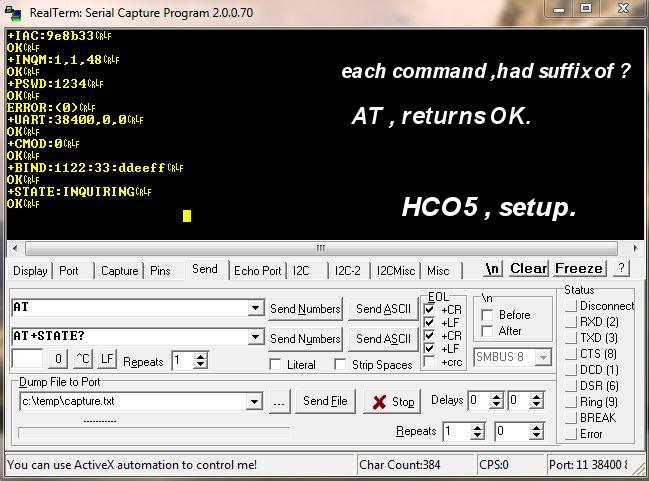
Now a SMARTERM, session:
I set the baud rate in the PORT Tab below, and opened the port. I then go to the Send tab, below, and send commands in the send box. I send "AT" cr/lf and get "OK" , you are in COMMAND mode.
Each module has a default baud rate, RTM. (38400,N,8,1) Use Windoz Device Manager to see the com port # , yes, it's that easy.
I'm sending the command to get into master mode here.
Sidetrack: RN41:
If using and RN41?, you send $$$ with no CR or LF , and must do so in 60 seconds of power up time. 60 seconds from USB cable connected.
The RN has no CMD pin /wire, only $$$ is used, to enter command mode. My RN connects in under 1second. It is very fast, after programming. (configuring..)
I found that Sw3 on my RN, autoconnect to my ELM instantly. is a DIP switch.
Back to HC05:
The below is a 15min session, and I only blipped, the command pin(key) for an instant to 3v. It does latch in, as the below proves! (open circuit on KEY = a Low, per BC4 doc.'s.)
I sent AT and get OK, I send AT+STATE? (as the manual states) and get Inquiring. (my slaves are all powered off) All commands below are ? asking mode. Not setting mode.
The Error was my adding spaces to end of command. That is illegal.
After programming, "configuring" reset power to see if it connects to a slave. Notice that the HC, it does not echo the AT command prefix , as seen below..
Remember to reset power, to get the commands to go into EFFECT ! It is all to easy to forget that.
All true commands are stored, you only need to train it (configure) it 1 time for a life time. (I only have 1 slave, so....)
This is enough information to get you started.
ALL MY Arduino CODE , so far:
- MPG via RN-41-EK (works on all Roving Networks RN41) (Gringo designed) (my best job so far) EK = engineers kit.
- MPG via HC-05, all kinds of HC. with hardware command mode. (HC= Hilarious Chinese?)
- MPG via SEEED BT 3030P , you could call it the Winchester of the famous lever action rifle, of same name. From China.
- Bluetooth Prep code,
here is just one standalone sketch , er', program that
programs (configures it as a master ,etc) on the RN-41. Runs one
time to set up and connect.
- The 1996 FORD ONLY OBD2 crank / cam sensor simulator CMP/CKP, ECU fooling program. Runs like a champ. 36:1 tone ring, timing.
- Project Voltage data logger, sketch.
The math: (yes, skip this ) " it's in my code, I tried to use pure simple Algebra, not C++ tricks or other magic. For readability."
Also , see it in my SEEED code. (beta rated?)
In my code, SEE MPH AND METRIC MILES , CALC'S in fact I did all Calc.'s in metric, then converted to Gringo (MPG), as the last step. Gringo miles and Gringo Gallons. (joking)
Simple 9th grade Algebra. (all values must end in Hours and MILE rates, thus the conversions below) See here, to learn what to expect. See VSS as PID at hex OD?
The items shown as words below (VSS), are PID variables (parameters) scanned.
The scan too reads them and crunches them and display them. This is what Computers excel at.
VSS = OD(hex) kmh Scan1
MAF = 10(hex) gr/sec Scan2
Then crunch this. Bida boda boom, display it, as Instant MPG. If you live in a real country? with real metric system ?,this is far more easy. As the ECU does report in metric. kmh and gr/sec.
MPG = (14.7 * 6.17 * 454 * VSS * 0.621371) / (3600 * MAF / 100) (process left to right)
reduced to MPG = 710.7 * VSS / MAF
14.7 - grams of air to 1 gram of gasoline - ideal air/fuel ratio This works only in closed loop mode, by virtue of the Oxygen sensor. ( if you know Stoich )14.7 Ratio and air flow?, then fuel rates can be calculated ,easy)
6.17 - pounds per gallon - density of gasoline
4.54 - grams per pound - conversion
VSS - vehicle speed in kilometers per hour
0.621371 - miles per hour/kilometers per hour - conversion
3600 - seconds per hour - conversion
MAF - mass air flow, rate in 100 grams per second (how much the engine sucks AIR, total (by mass grams, not volume)
100 - to correct MAF to give grams per second (PID RULE)
Even if your gauge is not 100% dead accurate, it will still tell you WHEN and WHERE, max MPG happens. (when to shift (early) and to slow down)
You could add a Close LOOP LED, telling you , you are wasting fuel, when not glowing, mine will. Mode 1 PID 03: "if not A4 fail"
Note that the MAF + ECU compensates for air temperature automatically, internally to ECU.
Some newer cars, you CAN get PID'S for actual fuel flow rates. MODE 1 PID 5E, Not my car. not most older cars, but my code runs on 17 years of cars.
If you have such a car, use that PID and VSS and bingo MPG is easy and more accurate. (car speed / fuel flow)= MPG ;
Keep in mind dead Accuracy is NOT Important, only Driving with MPG at max, regardless of absolute readings. (& closed loop active)
Or use both and report both or, average the 2? Do as you please.
For metric users, you only need to convert to liters, the air flows. VSS is km/h directly, and MAF is ((A*256)+B) / 100 = gr/sec. do this first. and you can skip the 100 in the above math.
In my code, I USB log both mpg and km / liter. that way you can pick the one you want. and stuff it to some Display.
My USB logger ,in the code called Logx, sends all data associated with speed and flows.(air/fuel). It's on by default.
I do hope this helps someone...
My Next Project :
MCU Voice Recognition (for inside automobile usage) Most likely ,just and enabling function. ( Fuel On, Tobor)
And CAN-BUS hacking my JEEP.
https://www.sparkfun.com/products/10963
Links, and supporting Doc.'s
The ELM327 chip, full doc.
All ELM data sheets. (real ELM not counterfeiters, of any kind)
RTM read the manual, RTDS, read the data sheet.
What is a PID...?
The Arduino UNO, I don't like the weak , loose/weak pins on PIO strips. not at all. (seems ok with shields but single wires, not)
rev 24 ++++ 8-23-2013 By :Ichabod Mudd , retired. New MPG project updates. major reduction. added digital scope view for 36:1 CKP tooth view. added facts for others to attempt this (by demand)