How to diagnosis the 1991 to 98 Factory Air Conditioning.
Sidekicks and Trackers. See relay facts & locations here and coil ohms checks and tests.
First and foremost, check the ELECTRIC SIDE FIRST! ( see very basic Freon(tm) loop tests here)
CHECK ALL RELATED FUSES!!!
Make sure the A/C belt has not fallen off or the tension set to zero, or minus (slips).?
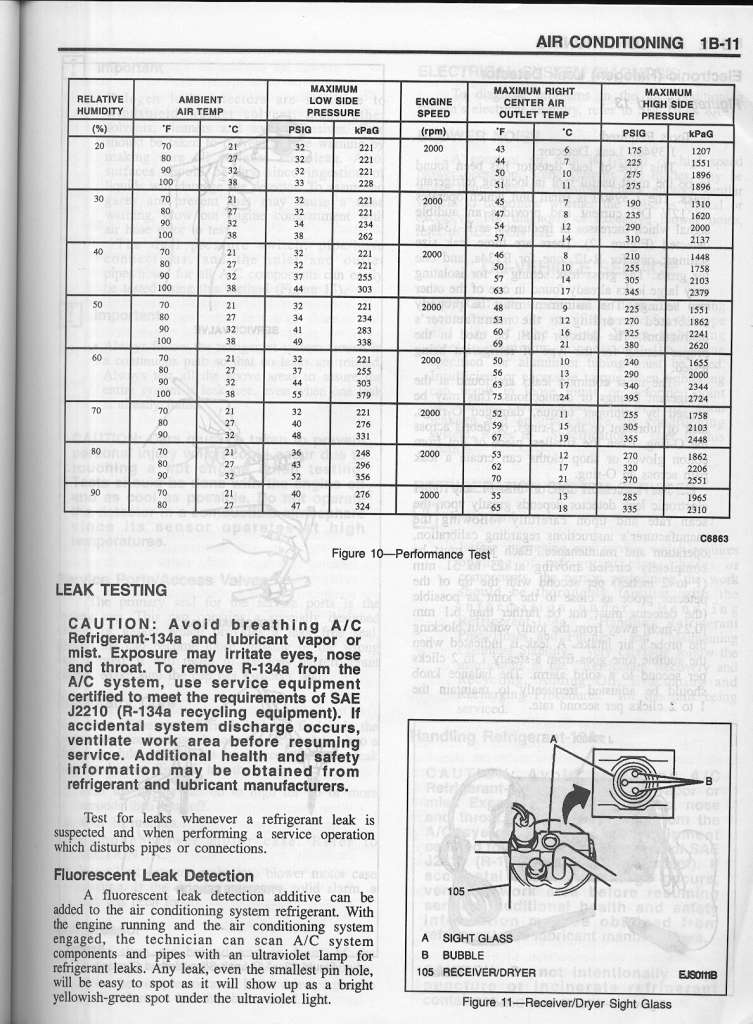
Check the Loop Pressure.
See this 96′ drawing and the warnings.
Before condemning the Freon ® loop, compressor or some other expensive part, try these tests first?
This document in no way, supersedes the FSM or any factory data. “Factory Service Manual” only $20 on Fleabay.
Do not HOT WIRE this system, take measurments with a voltmeter! or risk damaging the compressor!!! (dont say, I didnt warn you!)
This document is Short story, version. THE FULL STORY HERE with Freon coolant loop tests:
The system is really 3 systems, Mechancial, Electrical (electronics too) and the Freon Loop.
First find out which of the 3 are bad, it is easy to do, read on.
The following sensors and states of operation, can kill or greatly weaken, the A/C.
Put a portable fan blowing on front of car to test this system. (FSM way, for now skip that, this fan allows full performance testing.)
- Engine over heated or the A/C sensor ECT switch is bad ( ECT sensor 235°F switch activated for over heat or switch failure)
- A/C Freon loop has too high or too low pressure (HI/LO sensor switch). Spec is: Less than (91′) 30 psi OR over 382 PSI. (95′ it is, 28 and 455 psi)
- Engine is overloaded or is W.O.T. you are at wide open throttle, so the ECU in the car tells the A/C amp to kill A/C. ( FSM: see Speed control path)
- The Front fan is bad. In front of A/C Condenser coil. (low cooling effect but you will get full cooling at highway speeds) Just look? No magic to that.
- If the Evaporator core (cab) drops below 34 °F. ( because of Expansion valve error) the A/C AMP kills the A/C until core thaws. 37°F is the return back to normal point.
- If the ignition switch signals CRANKING falsely (cranking via start motor) this kills the A/C function. Bad wire is the only reason, or bad AMP.
- If Cab heater HVAC vent fan is off, A/C is now killed, if one of the fan controls is broken and fails to send Fan On signal. ( clutch opens)
- Outside air temperature must be above 50°F, ( I think this is only a test condition rule? ) Meaning cold weather testing is complex.
- Ambient temperture over 90F and humidty over 85% “performance will suffer” at high humidy, see 96 R134 chart!
The first rule is, does my Compressor clutch engage? You must look at it. the front of Part #1 below:
Rule 2: if the AC works great at fast road speeds, make sure that part 24 below is always spinning fast, A/C on. It runs real fast! AKA: condensor fan.
Never seen or heard of an A/C amp failure part 53 below.
The Hi/Low switch is at ID 35 below. ( it is electrically closed all the times, if freon loop is at spec) “ohm meter it?” zero ohms is expected.
Best practice, if you are fully confused, is to measure all the pins on the AC AMP with a voltmeter, the answer for electric shut down is now known!!!
RULE #3:
If ANY input to the A/C AMP are false ( wrong) the CLUTCH RELAY WILL DE-ENERGIZE! The A/C-AMP is just a Logic module, nothing more.
THAT IS ITS NUMBER 1 JOB.
This includes the evaporator core frezzing below 34 deg. F. ( dont worry this too much, this thermistor allows AC to cycle with the evap is too cold)
The front fan runs any time the A/C is turned on, if the out door temperature outside is below 50ºF the Front Condensor fan may? shut down on some years and marketed cars.
95 system photo: (typ. 89-98)

#23 is Condensor, #29 is receiver dryer with HI/LO switch on top., compressor is #1 and evaporator is #37 which contains the expansion valve too.
#53 is the AC- AMP, which never goes bad.

Data 91′:
Spec.’s:
Clutch Coil resistance is 3.2 ohms ± 0.2 ohms.
Thermistor (evap core) resistance is 5k ohms at 30 ° F and 2k ohms at 70°F. (prevents core freezed and blockup of ICE)
Loop High Side spec, is 200 PSI. @2000 RPM, Fan on High, Cooling at max.
Begin testing: (some years are missing some of these parts, see photos below and comments.)
(The 2 relays, condensor and clutch are located in the Fuse Relay Box, next to the battery.)
Check all Fuses first and use an ohm meter to test them never trust looking as a sign of good. (really a time and money waster not testing them)
The procedure is simple, make sure the Compressor clutch engages.
if it doesn’t, then check power to relay 4 above, no power input, then the fuse#1 is blown, if no power out of relay 4, it is bad or not being commanded ON.
If Power is present on the Coil of the of the compressor, B/W wire, then the coil is open or the ground strap is broken or rusted.
Lets assume the coil is good and the B/W wire is dead, now we check the Relay 4 coil wires.
( one can, hot wire the clutch coil to see if it works, apply +12vdc from positive terminal of battery, with inline 30 amp fuse) (compressor must pump) Page 1B9 FSM.
But do not hotwire any clutch until you know the freon loop is charged to spec. (do not run the compressor DRY or with out lube) do not.
The Yellow wire of sensor 6 must be tested next. if 12vdc is present then the HI/LO sensor is good if not, the freon loop is low or over filled.
I will now assume the sensor #6 (above) is good and closed inside. (it is just a simple switch). If no 12vdc on the Lg light green wire,then the fuse is blown.(next to Key above)
You have 12vdc on the Yellow wire, now check the P = Pink wire, this is the main Compressor command wire.
It (pink) must be grounded ( 0.5v or less), if it is?, then the Relay 4 (above) has an open coil or bad wires. ( the AC amp grounds this wire when it is happy)
( I will not mention bad wires or connections again, as this is obvious).and when I say 12vdc I mean 12.5 to 14.7vdc. (not running, and running)
When I mention 0volts I mean less than 0.5v ( suz spec)
Lets say the Pink wire is stuck at 12vdc, this means the A/C amp has detected a fault. ( A/C amp is bad or one of its inputs is in a fault condition.
Remove Glove box to find A/C amp module, bolted to the evaporator case.
All readings can be done with back probing techniques, on the connectors.
All readings taken with the Voltmeter black lead touching the metal body of car. GROUNDED.
There are 6 inputs ( 7 wires) that can fail, at the A/C amp. ( the AMP is just a slave, to these signals, it is just a simple logic module )
The amp does just 2 things, reacts to faults and regulates the evap core temperature ( antifreeze up logic)
Some Sidekicks 92 and 93, the AMP can be vastly simplier relay box. see schematic Link, at the end paragraph, of this document, for these 2 years.
I will now cover them (AMP conn. pins) right to left from above. (keep in mind the thermistor never fails, very very rare )
- The freeze thermistor must read less than about 3000 ohms (Y/G and W/BL WIRE PAIR). check cab evap. core for freezing if yes, the Expansion valve may be bad. ( when it thaws, the A/C will start working again, and if this is true then the problem is not electronic (AC Amp,etc).
- The A/C IS on wire must be at 12vdc, or the fan switch is bad or a connection in this area.
- The B/Y wire must be at 0vdc, if not, the starter circuit is sending the start signal all the time, a rare wiring fault for sure as surly the car is not cranking full time!
- The Lg wire is 0 vdc, and this is because the Ignition on wiring is faulty. Or the fuse is blown.
- The engine over heat A/C switch is tripped. 0vdc is ok, and 12vdc means the coolant is above 235°F or this A/C thermo, switch is bad. THE WIRE FELL OFF (a top fail)
- Last pin is the ECU logic pin Y/B wire. Called the Idle up pin. The A/C amp grounds this pin to tell ECU to Raise idle. ( the ECU may be able to send a signal no this pin, the FSM text alludes to this idea, for Engine overload etc, this can vary by year, model, country of delivery. “can be software related”
I did not mention the ground pin on the AMP. the “B” wire, and this must be 0.5vdc or less.
All it takes is a few moments to test the above logic pins with a cheap volt meter, this will for sure tell you if the problem is an Electrical Fault or the Loop is failing.
This concludes the electrical diagnosis, if the electrical is ok, then the loop is bad.
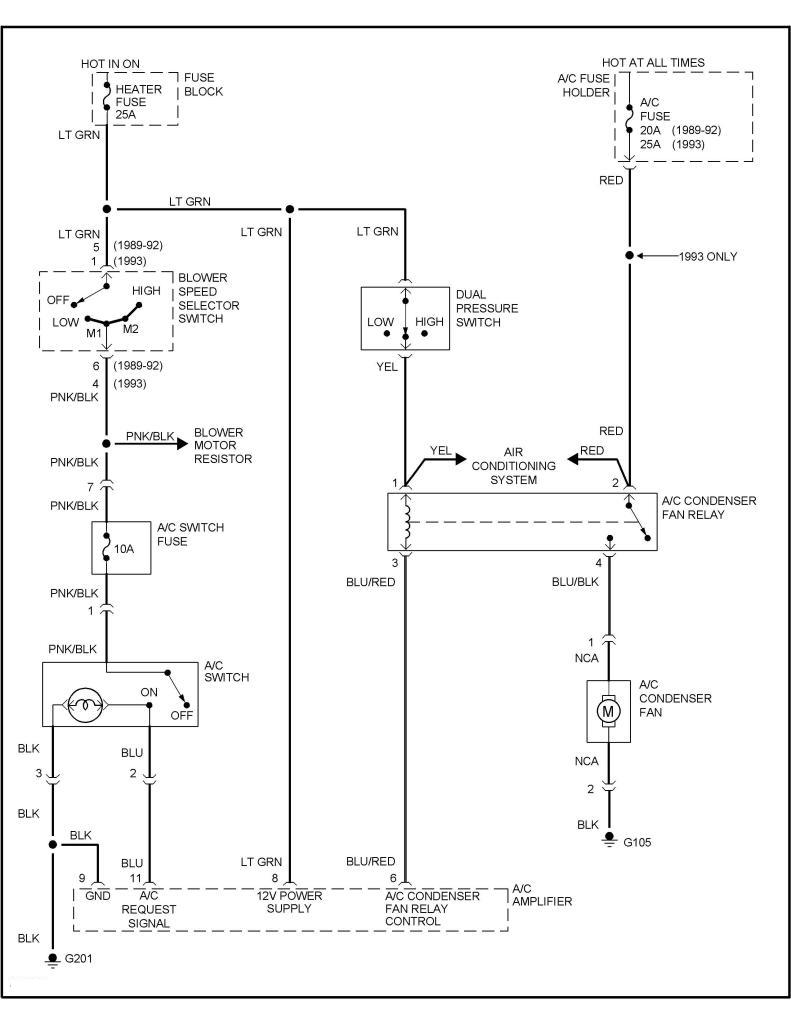
Note the 91 controls the condensor fan seperate from the compressor, not true on 94 /95, cars. ( the AMP decides, in unknown ways on 91)
Then in 1996/98 the Amp becomes more like the 91, controlling the fan independantly.
The shop manual has weak information on the Evap fan operation other that it seems to always spin, AC ON. ( there may be exceptions?) [eg: below 50F]
This document focuses on Sidekicks, and there is lots of information on the web on freon loop diagnosis, which I will not try to cover.
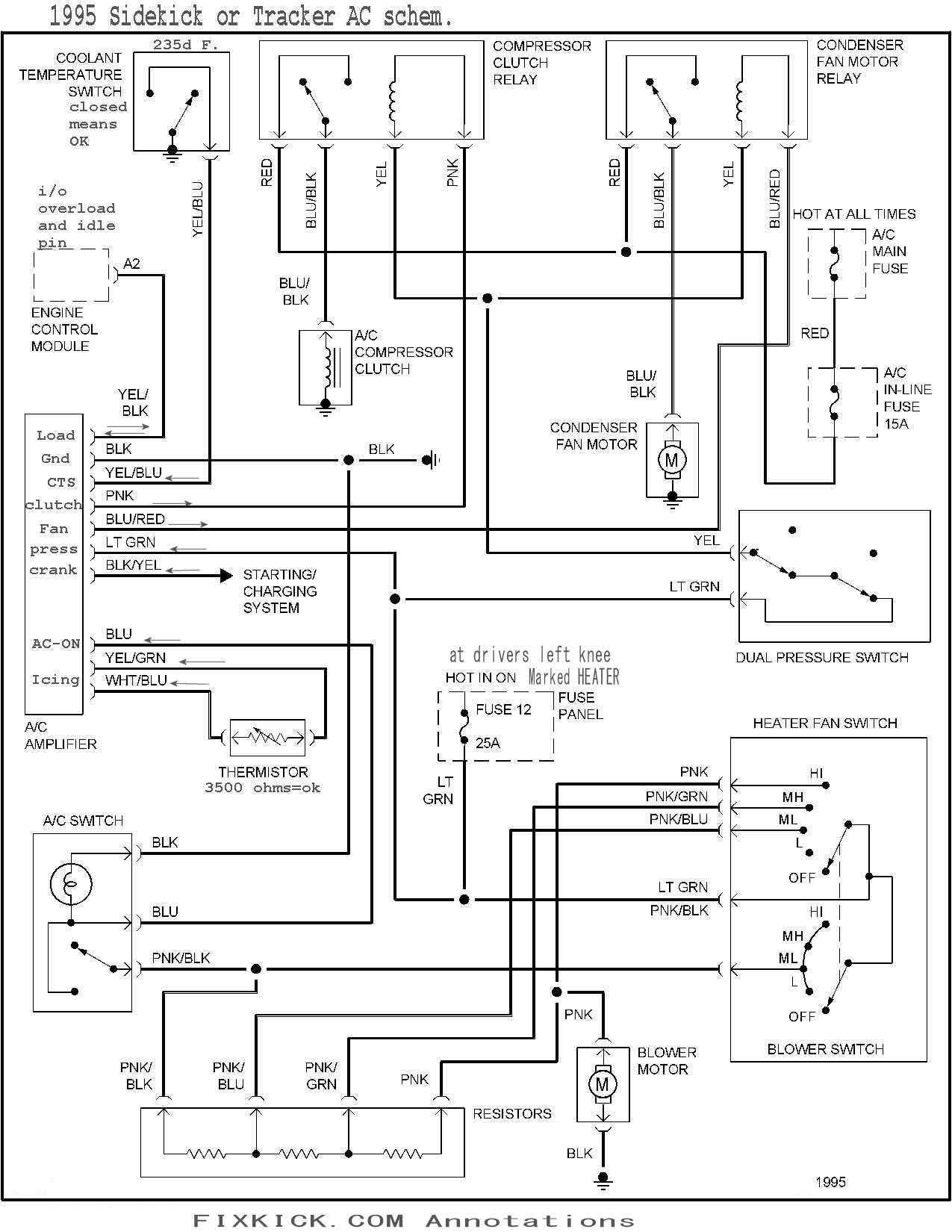
Here is the 95 schematic. 95 uses Freon R134a.
Click below to zoom it.
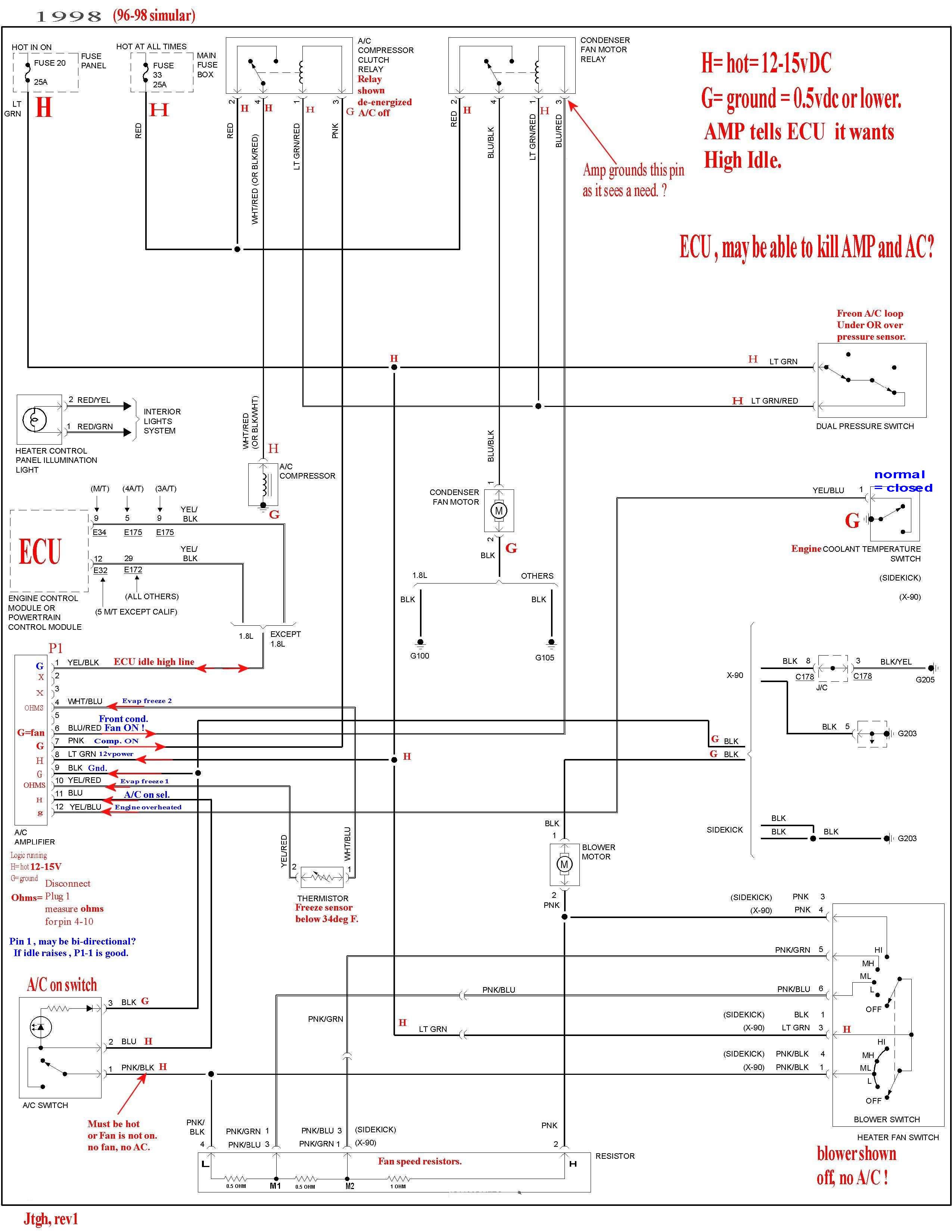
94 and newer look like below schematic.
the arrows pointing Into AMP are INPUTS!
The compressor unit. The coil is at #6 ID.

Rules:
Above, when clutch coil 16 is deEnergized with 0vdc, the nut 22 does not spin. nor 18.
DeEnergized 0v, the pulley 17, freewheels spins. With 12vdc at the coil the clutch locks and 18 spins.
17 always spins., if it stops the belt (not shown) will smoke and scream bloody murder.
That ground wire lug above,left of 23, if bad,loose or corroded, will kill all A/C function as will that connector below 23.
Last is a, 1998 A/C schematic: ( just about the same )
96-98 all look the same.
I think the cranking disable feature is missing. ( but might have been moved to the ECU side? of communications).
Click Below schematic to ZOOM:
 Click to ZOOM
The A/C AMP, was simplified for 2 years, 92 and 93 and looks like this.
In these 2 years,the AC amp is just a single relay.
See 3 black lumps, those are the relays. 2 are for AC. the wire colors will tell you which is which.
 ss
ss
the Condensor Fan and A/C clutch relay are the same Part number, which is Suz.# 38860-72G00 $30 each.
swap em, to see if one is bad.
MY very very ugly AC relay finder. Sorry.
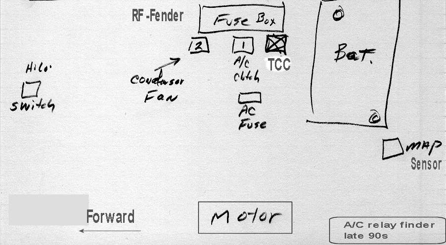
Best case A/C AMP logic: (not documented fully, Suzuki little secrets)
- All functions are killed if the A/C and defrost is off, (Yes, the A/C is a dehumidifier and removes water from the air, in Defrost setting of the HVAC)
- Kills Clutch /Compressor for Evaporator Freezing up, via thermistor inputs.
- Kills Clutch for Engine overheat or the wire fell off the engine overheat sensor (unique to A/C not part of EFI)
- Kills Clutch if ECU sends engine over load signal to A/C amp, eg: pulling a trailer up hill or just passing a trucks, at W.0.T. (wideopenthrottle)
- Kills Clutch if A/C is not turned on.
- Kills Clutch if you are cranking engine.
- Kills Condenser fan if condition 1 happens. (helps unfreeze Evap, quicker)
- Turn on Condenser fan, if the A/C is on and Ambient air temperatures, are over about 100F (my guess and mine does this!)
- Condenser Fan can come on, any time based on operational status of the A/C system, the AMP does on purpose, tries to rest the Compressor any time it can.!
- On some early AMPS the Condenser fan may be on any time the A/C is on.
- The amp may kill the A/C totally, if the out door Air temperatures are below the point the Loop Freon has any effect. “it’s dead anyway, so lets shut it down, <40F?
- If the Hi/low switch is open,the system will be dead. This feaure is a FAILSAFE, saving compressor from destruction, do not hot wire the HI/LOW!
Do not modify the system or hot wire the Hi/low switch and only hot wire a clutch engine off for a test.
If the relays are dead so will the object it controls, if the relay contactors are welded, the object it controls will stick on.
In many cases you can swap relays, Clutch and Evap Fan.
If the fuses are blow, the system will fail.
Some AMP’S do not have all the above features, 92/93′ and in some countries the whole system is different. The above is all 100% USA market cars E03.E33
Short cycling, is normal for the system, in mild summer heat. (saves wear on the compressor it does. but when real hot out, the compressor may run full time.)
The Loop ( I not going to cover the loop, this page I mand finds out if the electrical side is good. “yes, the Freon(tm) refrigerant loop”
If the Hi/lo switch trips, check pressure with this refill kit. ( remember, it can trip overfilled, and overfilled they systemhas less performance)
If the loop has lost pressure and repeats, you need to do a dye test. ( this is a DIY method too) the cheap UV lamp is here.
If the expansion valve is bad (say, stuck wide open), and over cools the Evap, the freeze sensor can cause false short cycling. and reduced cooling.
Conduct tests to find out the cause. (beyond my scope, here) See freeze thermistor in the schematic above.
If all else fails, RTM, READ THE MANUAL, the OEM factory service manual,near free, at about $20 USE on ebay. see my manuals page.
Some one asked how to replace the condensor (in front of main coolant radiator)?
First Evacuate the system per federal rules, then do this, a non trivial set of steps.
I am adding ac to my 95 sidekick. Does anyone have a picture of the ac condenser mounting. I have the brackets and parts I got from the wrecking yard that someone else pulled but for the life of me I can not see how they fit. Thank you.
бензол чда
Tegs: борная кислота хч https://aldosa.ru/chemistry/him-react.html
фруктоза гост
фтористоводородная кислота осч
хлорбензол гост
2 ацетилбензойная кислота
Tegs: 2 ацетилнафталин https://chimmed.ru/products/search/?name=2-ацетилнафталин
тригидрат ацетата свинца ii
тридеканаль
тридекан купить
mettler toledo
Tegs: рефрактометры https://chimmed.ru/products/laboratory_equipment?group=%D0%A0%D0%B5%D1%84%D1%80%D0%B0%D0%BA%D1%82%D0%BE%D0%BC%D0%B5%D1%82%D1%80%D1%8B
цезия хлорид
полисорбат 80 купить
флуоресцентные красители
октанол
Tegs: анемометр testo https://chimmed.ru/
пробирка купить
рифампицин цена
ионоселективные электроды