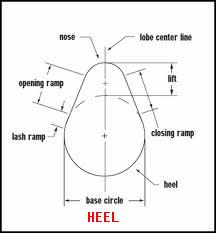
The below, is with out rockers for clarity. This car has solid lifters, and must never be set with zero lash or minus lash.
Lash is that space above the valve stims and cam. The back of the cam is the HEEL. The top is the LOBE.
The heel is perfect simi circle and lash does not vary here. (cam not wrecked, sure)
 A simulation of cam action only.
Assumptions:
You know how to use a feeler gage and have read books on the methods.
Cam is timed Exactly perfectly.
The cam cog has a good keyway and key and is indexed (fitted and locked) Not damaged.
The crank cog , is with a good key and is not mangled.
The Timing belt is timed to perfection.
The distibutor rotor (TDC) was timed at 11pm per FSM (the FSM uses the rotor to set lash , so if wrong, then WAY 1 FAILS)
Lash is always set last. If you refuse to follow these rules, the FSM and Way 1 will fail you. If you insist?,then do Way 3. It never ever fails.
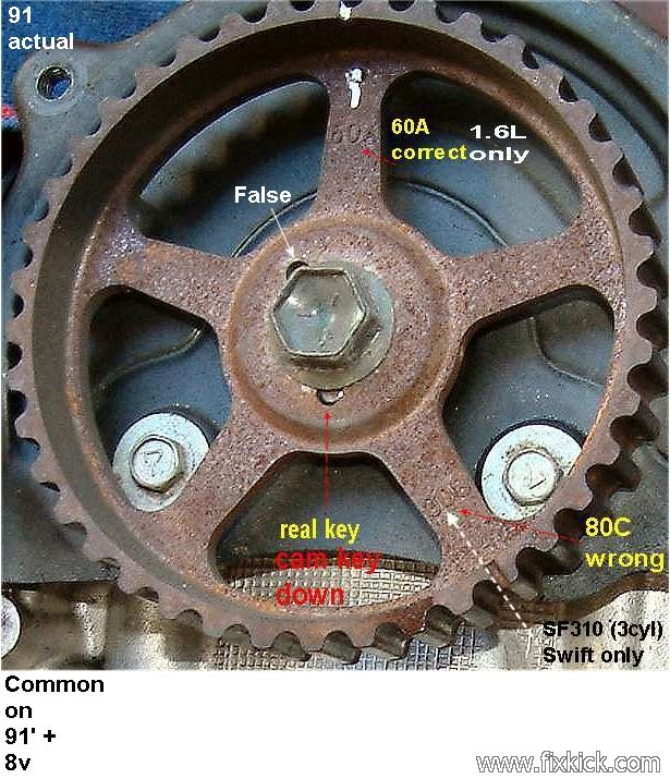
Warning in some years the 8v motor cam cogs, have false keys and marks (89/90 don't) use the 60A marks for the PIMPLE.
DO NOT USE 80C marks !!! The Pimple cam cog spoke, is early years.
Rules: CW = Clock wise, CCW = Counter clockwise (facing rear of car)
- Never turn the engine over with wrench using just the cam bolt.
- Number 1 cylinder is the front cylinder.
- Always spin crank bolt , CW, less you risk getting
the crank 17mm bolt loose.
- If you find the lash changing during a validation of
lash , you have set the valves , not on the heels or, a serious
mechanical failure is here.
- In each step you must tighten the cam rocker set screw jam nuts, to factory spec. "Cam valve lash lock nuts..... 11 to 13.5 ft/lbs or 132 inch/lbs"
- You dont need special tools, all tools mentioned here are to explain the tools shown in the FSM, I ignore them.
- Do not rely on the Disty rotor location or HV wire rounting, for this procedure.
(or risk FAILURE
and burned valves)
- The FSM uses the assumption, that all things are perfect, sure in a factory , perfect happens, but in a real world, NO!
The Lash can be set 4 ways.
Way1: The FSM 2 stop, Factory Cheaters way, is fast but ASSUMES (ass out of U and me) due to wild assumptions on Suzuki's part.
The way only works on PERFECT engines. Is yours PERFECT?
Failure points:
- Bad keyways, sheared etc, on cam or crank.
- Using dizzy cap rotor as a clue, fail.
- Using spark wire 1 as a clue , fail.
See full Way1 below:
The Suzuki way with just 2 crank turns
Way 2: ( Not looking at CAM COG wheel , way, nor Dizzy) Valve cover is REMOVED, only.
The 4 stops way( the crank fires every 180 degrees of rotation, 1,3,4,2 )
(cam not timed right is failure here, same for crank key, same with the infamous crank pulley internal rubber has failed and is loose)
Cam Cog not exposed. (cover on Tbelt not removed) I'm trusting all keyways in the engine, here.
This 4 stop way, I first put a chock mark on #1 crank pulley edge "V" mark, then put 1 more mark at 180 Degrees (1/2 turn around) on the same pulley crank. (about)
The #1 mark is for #1 firing and #2, the rockers are on the cam heels if #4 is on heels, now, I then t rotate the crank 360degrees and now #1 is firing. (#1 rockers on cam heels)
Some folks have compresion gauge on #1 spark hole to find when #1 starts buildiing compression and us this method to find , true TDC #1 JUG FIRING.
We set lash for Each cyclinder in this order, 1, 3, 4 ,2 (ignoring the distributor , totally)
Turn the crank only Clockwise.
#1 crank 'v' mark at TDC 0, cams on heels #1 , set lash on #1
Rotate crank 180 degrees CW set #3 lash.
Rotate crank 180 degrees CW set #4 lash.
Rotate crank 180 degrees CW set #2 lash.
your are done.
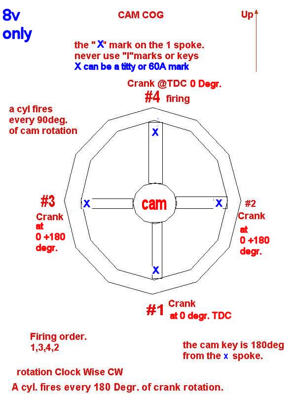
Way 3: THE CAM COG WAY (The key sheared or using the wrong key slot,is a failure here)
This way trusts the Cam cog wheel and key ONLY. The timing belt cover is REMOVED for THIS WAY/
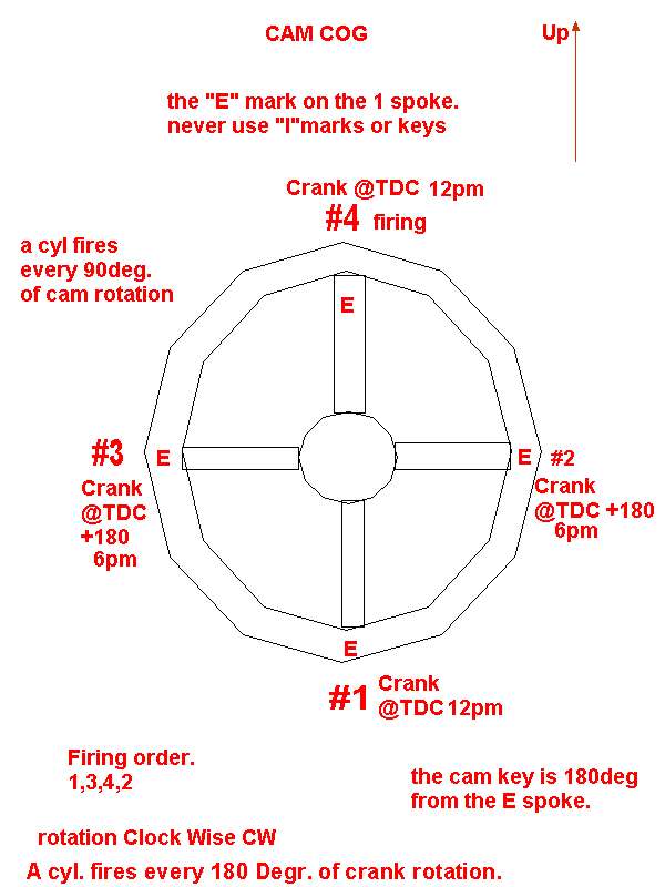
The Cam fires every 90 degrees of cam rotation and the crank every 180 degrees of rotation.
This other 4 stop way, I do Each cyclinders sets of valves in firing order, 4,2,1,3 ( same as 1,3,4,2 really, see that?)
I start at #4 because finding that is very easy. you can start at any cylinder firing. that is for sure.
The CAM mark (spoke titty or 60A mark) is at 12pm (#4 firing)
Turn the crank, CW and put that mark at 12pm, then glance at the #4 (rear) valve cam lobes, are they both on the heels, yes, good, no bad.
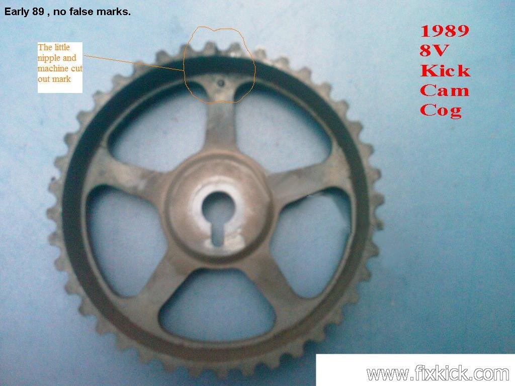
The 8v cam cog spoke only has a Titty / PIMPLE. or 1991 and newer use this (60A) spoke cog wheel.
Put the crank at TDC 0 degrees. and cam Pimple at 12pm , this is #4 firing. (our starting point.) I start at 4 because the Pimple is easy to see up top at 12pm.
Then set lash at #4 rear cylinder. both valves. (the cam will be seen at the heels. of #4 cylinder, look at the cam lobe with your eyes, see it?)
Steps: Turn the crank only Clockwise. (this direction keeps bolt for loosening) At any step, if the cam is not on the heels, it's a FAILURE moment.
order, 4,2,1,3 :
- Put the crank 'v' mark at TDC 0 on the scale, cams on heels #4 , set lash on #4 (rear cylinder) COG titty (60a) at 12 PM
- Rotate crank 180 degrees CW set #2 lash. COG titty (60a) at 3 PM
- Rotate crank 180 degrees CW set #4 lash. COG titty (60a) at 6 PM
- Rotate crank 180 degrees CW set #3 lash. COG titty (60a) at 9 PM
- your are done. (you could start at 1)
 click me to zoom
Way 4 , (LOBE HEELS WAY ONLY) This is the only way that is 100 % failure free, for LASH ONLY.
This way is , just rolling the crank CW , and you, watching the lobes and when the lobes are on the heels? , then set the lash,
This is the no books, no tricks, no cheating way, it is taught in all ASE classes, for checking cam timing or lash on any 4cycle otto cycle engine.
All you need is a feeler guage, and eyeballs on the cam lobes, to do the job.
Why do this?, if you have issues with the motor, doing this way, prevents valve burn up, no matter what is wrong with keys and rubber crank vulcanization. You can do this , then conscentrate on timing, bad keys and what not and get compression over 150psi.
SUZUKI FSM WAY 1: The Texas two step ?
Assumptions:
You know how to set lash with a generic feeler gauge and can remove and replace the valve cover gasket ( with a new gasket)
That the timing belt is not slipped or installed wrong. The cam must be timed correctly, if not DO THAT NOW.
You own a 17mm deep wall socket and matching wrench.
You checked the crank bolt , for 94 ft/lbs of torque (CW facing pulley) because they all seem to be falling off. (TSB) Horror
Alway turn crank CW so you don't run the risk of accidental loosening up, this crank bolt. Not a good thing due to above horror.
CW is clock wise.
- Gain access to viewing and touching, the distributor and
valves.
- Find your crank shaft timing marks and mark them with white
paint, located on bell housing in pre 90 engines and on front cover
91'+ years.
- Get a new valve cover gasket , because we never reuse gaskets, in a 5 star shop (LOL). Trust me it will leak, if you skip this step.
- Remove the spark plug wires from the spark plug tips, mark them so you know where they go back. (can't be mixed)
- With a17mm wrench, turn the crank shaft big end (front)
bolt
Clock wise , until the Timing mark on the pulley rim (notch) aligns
perfectly with the timing scale molded into the front timing belt
cover. 10 |||||5 |||| 0
<<< something
like this. set it to 0 degrees.
- Remove distributor cap ), mine has 2
screws. Mark #1 spark plug wire on cap with white paint or tape. And
Distributor base.
- Look at the rotor, is the rotor at 11pm ?
- Yes ? then jump to step 11.
- If not at 11pm, then rotate crankshaft again to CW ! 360 degrees ( 1 full turn on crank) and aligned again to 0 degrees.
- Is the Distributor rotor at 11pm. NO? then someone set it
wrong. You have 2 choices now ,
time it correctly or just mark the rotor to the body with
paint. If the Distributor is not
timed ( it was removed,
or the head or cam was removed, see this note1.
- If not sure? then you now need to check that the
valves are all closed at the front #1 cylinder pair. Intake
and Exhaust
valves must be on the back side of the cam lobes and loose. If
you can not get lash loose on #1 cylinder or not get the lifters to the
back side of lobes , then the cam timing is wrong. Correct the cam timing NOW.
- If you just want to get the lash done and forget the
Distributor timing, then follow one of the 5 steps in note 1 and then jump to step #14
- Note the Distributor can be timed in 4 positions, and
doing so,
is really bad practice , even though it runs perfect, just feel sorry
for the
next poor guy, trying to sort this deviance. If you find any issues
here , then re time the cam and then re-time the Distributor, then
last
set
the lash.
- The cam must be timed correctly
before doing the Valve
Lash.
 Rotor
at 11pm !
Rotor
at 11pm !- Next, adjust all valves marked in below sequence, using a feeler gauge.
- Adjust valves 1, 2, 5, 7 (not cylinder
numbers,but sequence numbers) See lash tables at end
of
document.

- Set the lash on each valve 1 at time (all 4 valves in
group) and do not
touch the others
yet, just set 1, 2, 5, 7 and stop.
- We are done with those 4 now , so just rotate the Crankshaft 360 degrees CW and stop at TDC 0 again.
- Adjust the valve lashes for 3, 4, 6, 8 and tighten all to 133 to 168 inch /lbs. ( each valve lock nuts is tightened, as you finish each)
- Do not go back can touch the other valves , unless you rotate the crank , 360 degrees again.
- This process is just 2 steps, at two TDC 0 deg. locations on the crank.
- The first step is really TDC #1 (1,2,5,7) and the second is TDC #4. (3, 4, 6, 8)
See below data for the lash spec.s and the valve cover torque.
Valve cover bolt torque is , 36 inch/lbs or 3 foot/lbs ( very very tiny value)
The LASH data:
| Valve |
COLD 69-77º F |
HOT 140-154º F |
|
| Lash |
INTAKE |
.13-.17mm .0051-.0067 in |
.23-.27mm .009-.011 in |
| specification 1991 8 valve |
EXHAUST |
.16-.20mm .0063-.0079 in |
.26-.30mm .0102-.0116 in |
What is TDC?, how to find it, etc.?
ver2