The EBAY express $100 , Cloned M.A.F revealed !

First blush, more test coming.
If this page scares you (it should) then buy a real Suzuki Maf , best sources is CARDONE.
The real MAF was instrument grade, that is, it must be dead accurate at W.O.T. (wide open throttle or when ever running ,OPEN LOOP)
If not ,bad things happen, if engine goes, lean you can burn up exhaust vavles so easy, or in this case, flodding to the max. (even at idle)
Is this clone up to PRIME TIME? (I think not.)
LID off: (customer said it's dead, and it is). New in the box too... from clonesville.."fleabay?". Not one auto store in my town sells this clone (they'd go broke on returns?)
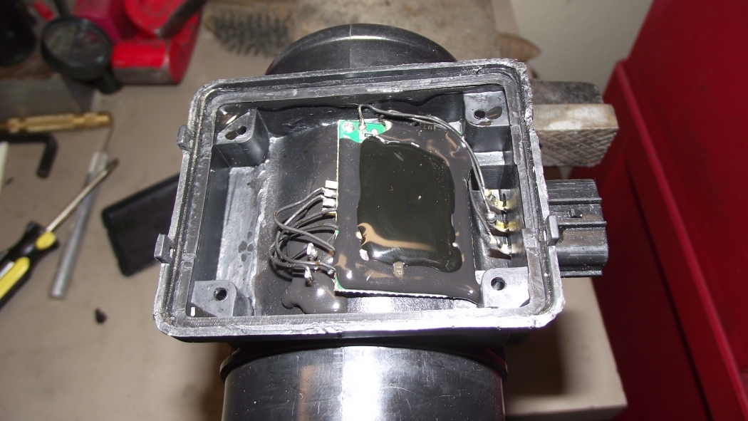
All Cleaned up, you get this next.: The below is the GREEN PCB , Printed Circuit Board. (with hand soldering flux aplenty)
How I reverse engineered it.
Quality?:
(a great first design in the whole , almost?, (forgetting 78L05 issues, < this part don't belong in cars.)
Good layout, but poor execution (and very weak production and QA "quality assurance and poor consistancy") No way ISO9000 quality.
I would rate it as Toy grade . (I have more tests to complete , after I fixed it)
It is not even cleaned after the assembly.
The hot glue, they used was over this flux, and was a waste of time, as that don't stick at all, and allows moisture to ingress in time, (fail soon)
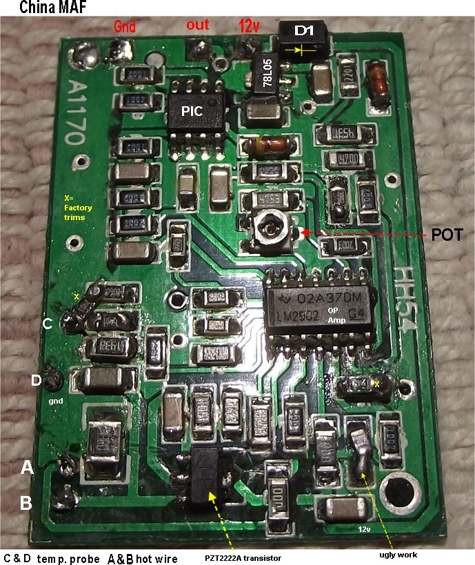
Active Parts inside:
LM2902 Op-Amp (x4 inside)
"PIC" 8bit processor with on board flash memory SMD > 12F683
78L05 , see ways to make this part not blow up here.
Transistor PTZ2222a IP1. 100mA =IC , Hfe=35-300 60v rated. This is the hot wire current driver. (wired wrong day 1)
Discovery:
No markings on the MAF for ID, only plastic type codes (case molding codes ) PBT-GF30 (Polybutene Glass filled...yada yada...
Only some Chinese script, on top. ( a recycling warning)
The MAF is AIR directional and has an Arrow on the case , showing the correct way.
Using any CAI modified system , I can see that putting the MAF in backwards would be easy, (missing stock mounts) CAI = Hacked Cold Air Induction mod.'s.
The unit has a PIC processor based chip (with internal flash EEprom)
This chip it is pre-programmed and with tables, for Vitara G16B dash58B00 flow rates. No marks on the PIC for programmed type !
The uP or microProcessor, is programmed to mimic the original Suzuki MAF air flow to voltage responses. ( we can only hope? )
The chip is programmed, before installation.
The unit. tests.
The 5v regulator still works great on the sample, and all chips receive the correct power. including the 12v to the OP-AMP.
The key on output is 1.5v. (stuck there, mostly)
The OP amp drives this pin via LM2902 pin 14, at 1.5v out of MAF the op amp drives 2.13v on pin 14.
There is a trim pot that controls gain of pin 14 , OP-AMP letter C.
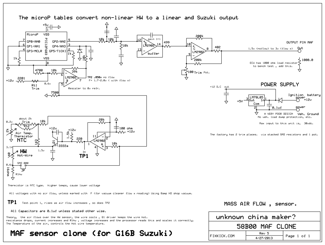
I made a full schematic , see it below. and a full resolution drawing too. (the middle layer is very hard to discover, so I will make errors)
The low bench tests. crude but very effective up to 1/2 throttle.
This bench test fails ! the output is 1.5v at all times. even with my simulated 1/2 throttle flow bench (about 40hp?)
But, ?
I fixed it.

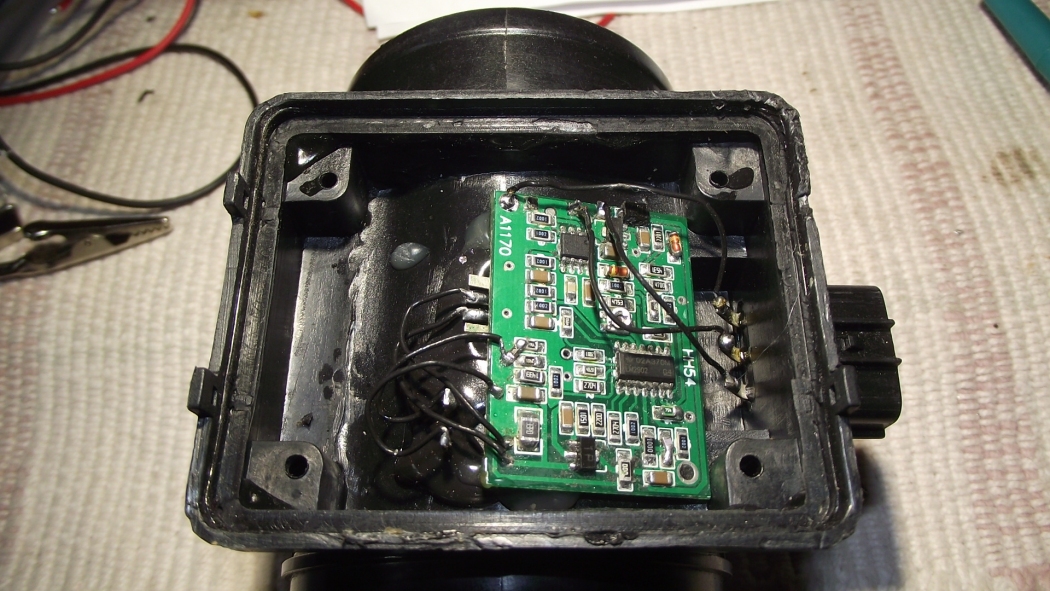
The solution !
I discovered that in the factory, the dimbulbs, connected the thermistor and hot wire, backwards inside. transposed ! (I have photos before and after, so have proof)
The unit is hermetically sealed so , it was factory virgin too. (thermosealed (plastic melted to lock the lid seal) "water tight, but not air tight"
After correcting that blunder, the unit now works.
For sure, it woke up. (at least it matches, my real MAF, with same vacuum cleaner suck action) It is linear and the hot wire started working for the first time.
Up to my 3 vdc output test with my HD vacuum cleaner.
Below is my new Schematic. (for High Resolution, see this HR file)
I don't like the Rt1 trim, using battery voltage , not at all. The trims are factory trim SMD resistors stacked up, to attain a desired bias.
They should have used a zenor diode here. (at Rt1 ) resistor trim #1) to regulate this bias point. The MAF is battery voltage effected.
Back together (cept lid)
Conclusions (so for ) :
I'd use it offroad, only, due to the weak, 78L05 chip. (it won't last) but see below, for a way to make it better.
You can in fact, just unplug it and let the ECU slam to Failsafe and MAF MIMIC mode, many find this good enough to run off road or pull stumps in the back 40.
I will never tell you , how to run YOUR car, only what happens in limphome (horrid MPG).
I have not completed all my tests, this unit, it don't like battery voltage changes, (bad that is) and I have not done the thermal stability tests, (heating/cooling, just the PCB)
I plan to test the MAF at 10v (cranking volts or dead alternator and car runs till battery dies, test) and at 15v.
I plan to do WOT testing (wide open throttle, I plan to use my V6 engine running and then remove the air cleaner and add the above and run it up to max. Later next week.)
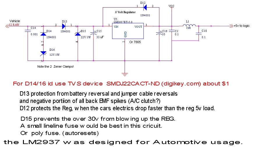
The 78L05 will blow up easy with out D12, so add a 2 cent diode (easy to do) across the input to output and a TVS device seen below.
This 5vdc regulator. (cheap and very not up to, car usage) see below for how others construct an ECU 5vdc supply. See 7805 warning text here.
The below is how to make the above better,
If you want cheap serious protection?, add this new TVS part, added to the 7805 input and ground for $1.
The SMDJ (TVS) can suckup 1kw pulse at 10mS, see data sheet.!
Better , is to Add D12 and a TVS in place of D14/16 the below D16, is ok but is rated at 10amp surge for 8ms. (longer spikes, way less)
http://www.digikey.com/product-detail/en/SMDJ22CA/SMDJ22CACT-ND/2409345
I'd put the TVS soldered directly across the MAF pins 1 and 3 inside. (easy mod) Seen above those 2 pins.
Below is what can be found in a new ECU. Add the TVS and delete D14,15, and 16. Below:
If you blow the Input section to the 78L05 and it shorts.. the microprossor, will thne blow up at 14v from the alterntator now direct to the PIC processor. ouch.
This fact, is the weakest link here.
The below is typcial car rated , power supply, used in ECU's.
Note the attention to stopping noise/surges and load dump glitching. and the low drop out LM2937 !
Note the L1 coil , keeping high frequency noises, out of the down stream processor. Not saying copy that , am saying see the techniques.
The 7805 , hates having the vehicle voltage drop before the pin 3. This blows up the 7805 , so easy. D12 stops that dead. Do not skip D12 modifcation.
If you get this MAF to work, just put in D12 and the TVS and it will run good and long. IMO.
The below is just an example of a working design. (used in race cars, and even holds land speed records)
It is so sad, how the China makers, do not bother to mark the MAF CASING, with a NAME and any part number at all , making it impossible to track it.
It's what I call a bottom feeding flounder part (fish joke) but the joke is on us, really. YMMV (your maf may vary)
More testing soon.
Later: work: (thermal, voltage (WOT) and vibrational testing, and a V6 suction test) before 5/10/2013
Enjoy!
fixkick.com
Special thanks to Gorky , for the sample ! (Gorky new maf works perfect)
Forum questions or sad stories, invited. (posts, PM mail , any mail)
ver4 5-8 -2013