
Testing the CMP 8 valve motor shown. (or cam angle sensors)
No spark? If this signal is dead, the ENGINE will never ever run.
(not valid for earlier USA 1989/90 VR type CMP senders) [variable reluctance type, nor for CPK crank sensors. they need a scope to see VR coil outputs]
The 16valve engines with a dizzy, have different pin outs, but this still works with them too at the white wire. (see end of page.)
You have 3 ways to test this CMP signal, the LED below, A DMM on volts range, or a Scope (DSO)
The store bought LED tool , is here, see Amazon listing for $3
The LED Test way, is a bench test below, the other 2 ways DMM and DSO, are on car connected. (must be) the ECU has a pull UP resistor to 5v and must be present or the output is dead.
The LED tests satisfiies that rule.
This signal toggles 0 volts. >5v > 0v and repeats, as you crank. very slowly.
OFF car only, on car can be done but you need to crank engine, with the connector below pulled off. Using any 12v battery at the blue pin. and grounded at black pin.
You can test with wire, live cranking, connected to cars harness as normal but you should use a DMM on the 20v scale to do this.
The DMM with an LCD simulated (All Fluke meters have this) bar, the bar will go to zero then 5v and back, as you crank.
The below is just for easy bench testing. 6 cent LED and a 12v battery of any kind or 12vdc power pack, or Wall Wart 12vdc.
Step 1: Pull Dizzy connector harness to Dizzy. Connect the LED and a battery as seen.
Make up one of these, any color LED will work. (they sell LEDs with the resistor inside already, for 19 cents each)
The long lead is + and the short lead is minus. The plastic head, has a flat side,that is Minus side. Im using cheap low power, LED here, not High power.
The below comments are for others trying to use this LED as a NOID lamp, (injector test lamp) This test device can be used, for many diagnostic purposes. for 6 cents.

The resistor is best to be about 470-650 ohms. Any wattage resistor will work. Any percentage. This resistor limits current to about 10 to 20 MilliAmps, 20mA max.
(the non resistor LED can explode of connected directly to a power source)
Resistor Color codes, the most common there is, (near) is this old phrase "Bad boys R................."
code: black,brown, red,orange yellow, green,blue,violet, gray white, (0-9) (gold silver none) 5% 10% 20%)
Green Brown Brown , is a standard color code and common. 510 ohms . 5 and 1 and 1 zero.
Step2:
With Distributor unplugged ,like below,
(assumes I am using a 12dc battery of any kind. ( a 12vcd power pack will work too, but it must be filtered and regulated)
A battery works best.
connect 12vdc to the Blue wire (center) of the Distributor conn. (plus battery lug) ( use an inline fuse on this lead ! 2amps slow blow)
connect ground or the other side of power source (minus lug)
The Distributor is now powered up.
Step 3:
Connect the LED plus lead to the blue lug PLUS center with battery lead,. ( all polarities must be corrent, no room for error here)
Connect the LED minus pin to the White top pin.
Step 4:
Four little steps , but are simple.
Now spin the Distributor gear ( cranking works, but out of engine, just spin it with your fingers ,seen in this video)
No danger of shock , 100% low voltage here.
The LED will flash bright ,then go completly out, 4 times per revolution of the Distributor. 2 of crankshaft.
Never connect the battery directly to the white pin, or the CMP will blow UP.

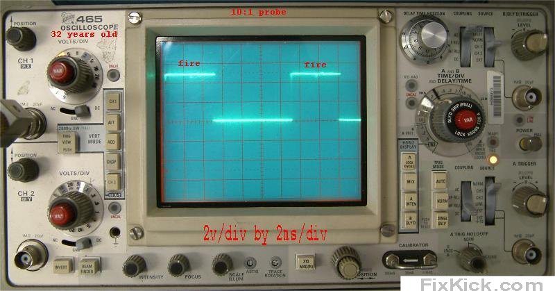
One can substitute any Scope and get the below images. This is a 35 year old scope proving that cheap scopes work great on cars.
This is on car test below, with the cable harness connected, to dizzy , key on, and cranking or running, below is running.
I'm just backprobing the white wire, nothing more.
All 1.6L Suzuki's from 91 to 98 have a CMP wire at the Dizzy pins. (no 89/90 has this)
My $50 scope. It now has an upgrade to LED x10 and X1 indicators, and LED Scale Illum grid. life time upgrades.
My other scope is vastly more accurate and overkill.
Note color codes of wires and figure out where to connect the LED above:
Any scope in the world can in fact read the CMP signals, they are slow, low voltage and no noise, or pikes. As see above. If this signal is dead, the ENGINE will never ever run.
16V pinout drawing: 92-95 ,the whole EFI sys. including the Distributor.
See the "white wire", yes, scope that wire for CMP signals. on all 1991 and newer Suzuki's with any distributor.
96-98 Pinout drawing of Distributor.
One Example:
Why would the CMP be dead. 8V 1991+
1: Cam doesn't spin.
2: Power to Dizzy dead. not 12v but 0v?
3: Ground wire to dizzy not connected.
4: ECU bad (extremely unlikely)
5: wire as pin 1,2,3 are cut, broken , or corroded or damaged at DIZZY.
Scope city:
If you buy a dirt cheap DSO , be sure to use a 10:1 10x probe or the cars natural inductive kickbacks (EMF, back EMF ) pulses will, in fact blow up the Cheap DSO inputs.
The above scope here, is good to 500x10 =5000vdc with probe.
Many cheap DSO are limited to 50v to 90v. max inputs, with the 10x probe that can be 500v easy,
Dirt cheap means about $100
ver 2: