The generation 1 distributor does not use the ECU at all , to create spark, in any way! ( do not read this page for newer generations)
It is a standalone distributor. This means you must validate both advance mechanisms like all cars 1920 to 1988, the centrifugal and the vacuum advance are pure 100% PHYISCAL and MECHANICAL.
How ever the ECU does monitor spark (crudely) and kills all fuel injections if the ECU dizzy signal at pin A1, goes dead.
There is no timing freeze jumper on this TWO YEAR CARS, because of the above rule. In fact you can time it just like a 61 Chevy.
There is NO CMP sensor inside the DIZZY, like on 91 and newer cars. This dizzy makes its own spark with its own, VR sensor and built in IGNITOR, and advances with RPM and Vacuum changes.
This pages assumes you know how to use a strobe type ignition timing light, and that you know , the Dizzy spins Clock wise and the crank spins Clock wise (looking at pulley)
And that the markes are clear.
The timing is set to 8 Degree's before Top Dead center #1 firing. Hot and at 800 RPM idle 8 BTDB (the centrifugal advance goes to at least 15 degrees at 3000 RPM then vacuum advance will do 5 more)
Before TDC means to the left side of 0 on the cover scale. (before means , advanced timing, that is the spark happens before TDC) Retardation is spark after the 0. (to the right and off the scale)
The timing must not jitter or bounce or the vacuum side is loose (pinch its vacuum hose to see if bounce stops) or the advancing weights inside the dizzy are loose.
Refr" FSM 6D4,pg-8"
Cylinder #1 is the front Cylinder. (Noobs ask, sorry)
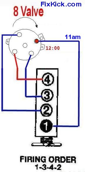
Firing order is 1,3,4,2. The FSM states the Base movement CCW advances the timing , the means the rotor turns CW (figure 16 in FSM confirms this)
#1 dizzy cap, SPARK WIRE is nearest the base clamp bolt 11PM, I call this. ( spec location) #3 is CW from this location and so on ...
Steps to timing the dizzy. ( fine tuning, see photo and drawing at end for course adjustments )
- All accessories off (head lamps, Fan and electric
defroster, and A/C off )
- HOT motor 180F or above coolant.
- Idle at 800 rpm plus or minus 50rpm, if not correct idle speed now. (at throttle stop plate screw)
- Connect the timing light to #1 front spark plug and to the
battery as the strobe manufacture directs you. Harbor Fright has this
tool for $15 to $20 (sale, no sales)
- Point the srtobe to the Timing belt cover
lower scale , looking down left is advanced , called BTC beforer
top dead center and count the slash marks to find 8 Degr. BTC. 2
deg. per mark. (4 x2 =8 so 4 marks advanced.
- Loosen the dizzy clamp screw a tad and rotate the dizzy unit the timing is at 8 Deg. BTDC. Clockwise dizzy movement retards the timing. Ths right of scale is Retarded timing.
- Tighten the dizzy clamp screw to 11 ft/lbs , recheck timing.
- A Pro mech will check that both advance parts in the
dizzy
operate up to 3000 RPM. (is vacuum canistor leaking ? and
does it move? and is the Centrifugal walking the advance out to near 18
degr at 3000 RPM (note1)
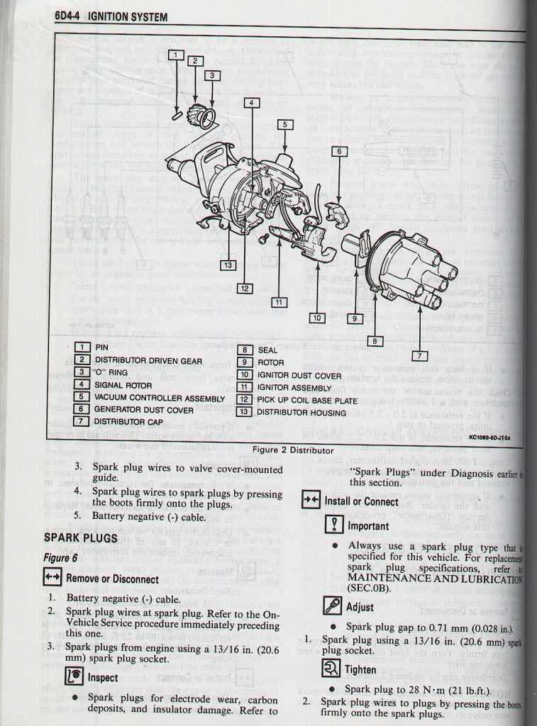
Distributor mechanical advance check.
dizzy cap off.
Grab the rotor and gently twist rotor against the advance springs Clock wise and then release it. If this action fails, these parts are rusted and jammed, take apart, clean and lube it until it works right.
Vacuum advance:
Cap still off dizzy.
Apply 16 inches (HG) vacuum to the vacuum nipple of the vacuum advance. The base plate must advance smoothly. {HG means Mercury in Latin. that is a murcury column of vacuum, USA standards. ROTW uses BAR}
Test 2 , stop pumping with hand tool and wait 1 minute, to do a leak down test, on the diaphram, it must not leak down .
All Tests are complete here. Put back the vacuum hoses.
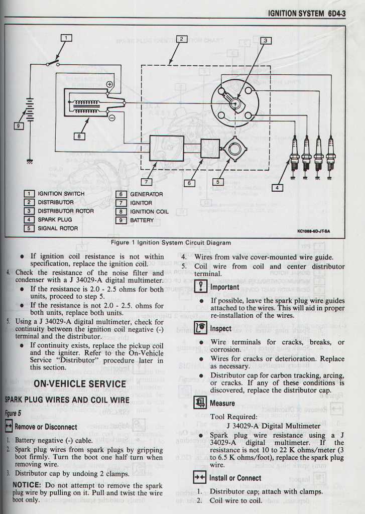
VR Sensor GAP: (shown as Generator below)
Adjust the gap to .008-.016 inches.
Turn crank shaft so that the VR rotor on dizzy shaft is 5 is pointing to #6 VR.
Lossen the VR base screws a tad.
Using a flat blade screw driver tweak the VR sensor so that the gap is close to .012" (8 to 16 thou)
Tighten the base screws on VR and recheck the gap.
Notice how there is no ECU shown below. How ever the ECU does monitor pin (minus coil).
The dizzy below can make spark cranking with the ECU parked on the work bench.
FSM pages.
Common failures are a dead VR or Ignitor and are $250 replacements. ( and comes in sets ,not seperated !)
The best repair (cheaper) is a used Distributor or a Rebuilt from Rockauto.com
Always play with the gap settings before condeming any dizzy.
Drawings:
See Figure 16 for Direction and wire locations. See VR test with a voltmeter and last , how to plant the removed Distributor.
Elaboration on step 5:
Direct the distributor in to the base hole, and anticipate the dizzy gear direction as it engages the cam gear ( helical cut gears) repeat the dropping
unit the rotor alignes perfectly with the #1 cap terminal (make #1 marks on to the base of dizzy with paint)
As you drop said dizzy into said hole, keep the dizzy mount in the center of its range. (Slot to clamp bolt alignment , centered)

Note: 1: finding advance curves for 89 Sidkicks is a hard won act, I can only find the Samauri at 18 mech. advance at 3k. Im sure vacuum adds to this and the 8 initial of 26 , add vacuum at lauch and add maybe 5 more? I dont now but I can sure look.

rev 3 ++++ 11-3-2010, added more noob stuff and the advance limits (15 and 5)